DESCRIPTION
The LTC6820 provides bidirectional SPI communications between two isolated devices through a single twisted pair connection. Each LTC6820 encodes logic states into signals that are transmitted across an isolation barrier to another LTC6820. The receiving LTC6820 decodes the transmission and drives the slave bus to the appropriate logic states. The isolation barrier can be bridged by a simple pulse transformer to achieve hundreds of volts of isolation.
The LTC6820 drives differential signals using matched source and sink currents, eliminating the requirement for a transformer center tap and reducing EMI. Precision window comparators in the receiver detect the differential signals. The drive currents and the comparator thresholds are set by a simple external resistor divider, allowing the system to be optimized for required cable lengths and desired signal-to-noise performance.
FEATURES
AEC-Q100 Qualified for Automotive Applications
1Mbps Isolated SPI Data Communications
Simple Galvanic Isolation Using Standard Transformers
Bidirectional Interface Over a Single Twisted Pair
Supports Cable Lengths Up to 100 Meters
Very Low EMI Susceptibility and Emissions
Configurable for High Noise Immunity or Low Power
Engineered for ISO26262 Compliant Systems
Requires No Software Changes in Most SPI Systems
Ultralow, 2µA Idle Current
Automatic Wake-Up Detection
Operating Temperature Range: –40°C to 125°C
2.7V to 5.5V Power Supply
Interfaces to All Logic from 1.7V to 5.5V
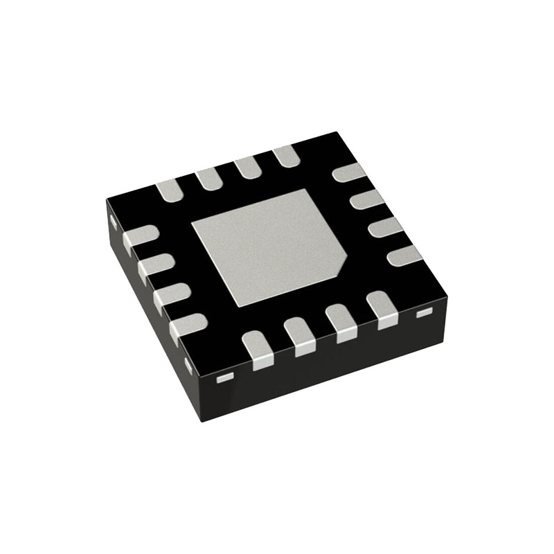
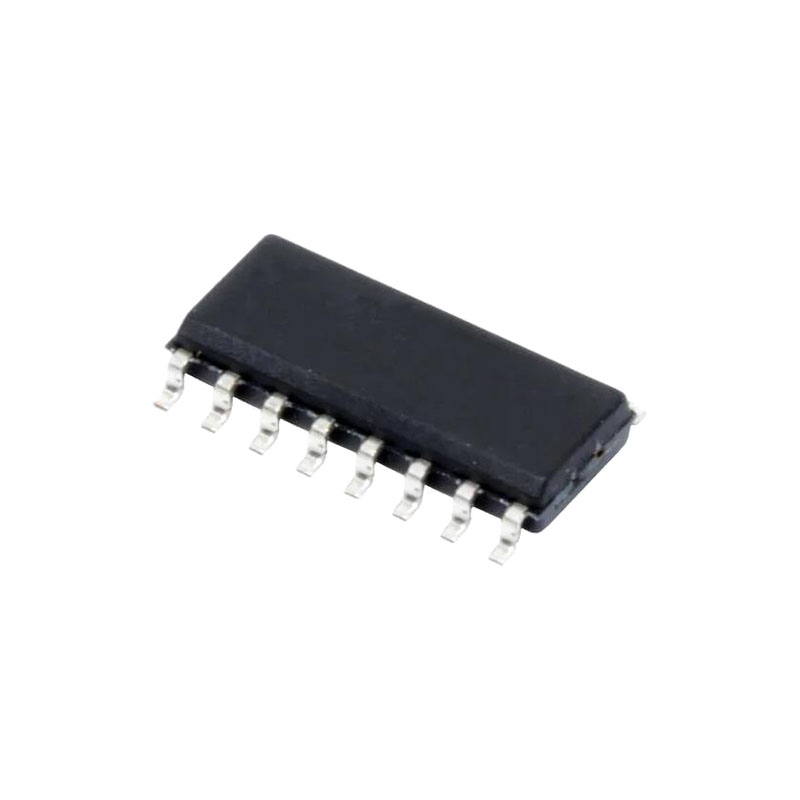
Available in 16-Lead QFN and MSOP Packages
APPLICATIONS
Industrial Networking
Battery Monitoring Systems
Remote Sensors
OPERATION
The LTC6820 creates a bidirectional isolated serial port interface (isoSPI) over a single twisted pair of wires, with increased safety and noise immunity over a non isolated interface. Using transformers, the LTC6820 translates standard SPI signals (CS, SCK, MOSI and MISO) into pulses that can be sent back and forth on twisted-pair cables.
A typical system uses two LTC6820 devices. The first is paired with a microcontroller or other SPI master. Its IP and IM transmitter/receiver pins are connected across an isolation barrier to a second LTC6820 that reproduces the SPI signals for use by one or more slave devices.
The transmitter is a current-regulated differential driver. The voltage amplitude is determined by the drive current and the equivalent resistive load (cable characteristic impedance and termination resistor, RM).
OPERATION
On the other side of the isolation barrier (i.e., the other end of the cable) another LTC6820 is configured to interface with a SPI slave. It receives the transmitted pulses and reconstructs the SPI signals on its output port. In addition, the slave device may transmit a return data pulse to the master to set the state of MISO.
A slave LTC6820 never transmits long (CS) pulses. Furthermore, a slave will only transmit a short –1 pulse (when MISO = 0), never a +1 pulse. This allows for multiple slave devices on a single cable without risk of collisions.
Setting Clock Phase and Polarity (PHA and POL)
SPI devices often use one clock edge to latch data and the other edge to shift data. This avoids timing problems associated with clock skew. There is no standard to specify whether the shift or latch occurs first. There is also no requirement for data to be latched on a rising or falling clock edge, although latching on the rising edge is most common. The LTC6820 supports all four SPI operating modes, as configured by the PHA and POL Pins.
isoSPI Interaction and Timing
A master SPI device initiates communication by lowering CS. The LTC6820 converts this transition into a Long –1 pulse on its IP/IM pins. The pulse traverses the isolation barrier (with an associated cable delay) and arrives at the IP/IM pins of the slave LTC6820. Once validated, the Long –1 pulse is converted back into a falling CS transition, this time supplied to the slave SPI device. If slave PHA = 1, SCK will also leave the idle state at this time.
Before the master SPI device supplies the first latching clock edge, the slave LTC6820 must transmit the initial slave data bit SN, which it determines by sampling the state of MISO after a suitable delay.


