ALLGEMEINE BESCHREIBUNG
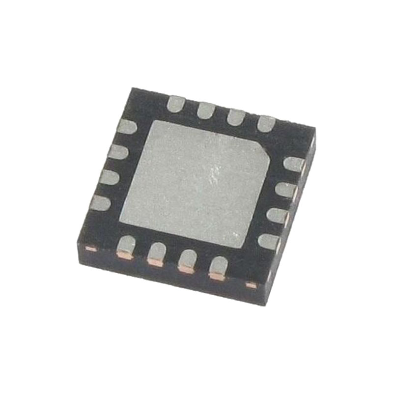
Der ADL5387 ist ein breitbandiger Quadratur-I/Q-Demodulator, der einen RF/IF-Eingangsfrequenzbereich von 30 MHz bis 2 GHz abdeckt. Mit einem NF = 13,2 dB, IP1dB = 12,7 dBm und IIP3 = 32 dBm bei 450 MHz bietet der ADL5387 Demodulator einen herausragenden Dynamikbereich, der sich für die anspruchsvollen Anforderungen der Infrastruktur-Direktkonvertierung eignet. Die differentiellen RF/IF-Eingänge bieten eine gut verträgliche Breitband-Eingangsimpedanz von 50 Ω und werden für eine optimale Leistung am besten von einem 1:1-Balun angesteuert. Der Ultrabreitbandbetrieb wird mit einer Divide-by-2-Methode für die Quadraturerzeugung des Lokaloszillators (LO) erreicht. Über einen weiten Bereich von LO-Pegeln wird eine ausgezeichnete Demodulationsgenauigkeit mit Amplituden- und Phasenabweichungen von ~0,05 dB bzw. ~0,4° erreicht. Die demodulierten In-Phase- (I) und Quadratur- (Q) Differenzausgänge sind vollständig gepuffert und bieten einen Spannungswandlungsgewinn von >4 dB. Die gepufferten Basisbandausgänge sind in der Lage, ein 2 V p-p Differenzsignal an 200 Ω zu treiben. Das vollständig symmetrische Design minimiert die Auswirkungen von Verzerrungen zweiter Ordnung. Die Leckage vom LO-Port zum RF-Port beträgt <-70 dBc. Die differentiellen Gleichspannungsabweichungen an den I- und Q-Ausgängen betragen 60 dBm bei. Der ADL5387 arbeitet mit einer einzigen Versorgungsspannung von 4,75 V bis 5,25 V. Der Versorgungsstrom ist über einen externen Widerstand zwischen dem BIAS-Pin und Masse einstellbar. Der ADL5387 wird in einem fortschrittlichen Silizium-Germanium-Bipolar-Prozess von Analog Devices, Inc. gefertigt und ist in einem 24-poligen LFCSP-Gehäuse mit offenem Paddle erhältlich.
FEATURES
RF-Betriebsfrequenz 30 MHz bis 2 GHz
LO-Eingang bei 2 × fLO 60 MHz bis 4 GHz
Eingang IP3: 31 dBm bei 900 MHz
Eingang IP2: 62 dBm bei 900 MHz
Eingangs-P1dB: 13 dBm bei 900 MHz
Rauschzahl (NF) 12,0 dB bei 140 MHz 14,7 dB bei 900 MHz
Verstärkung der Spannungsumwandlung > 4 dB
Genauigkeit der Quadratur-Demodulation Phasengenauigkeit ~0,4° Amplitudenausgleich ~0,05 dB
Demodulationsbandbreite ~240 MHz
Basisband I/Q Antrieb 2 V p-p in 200 Ω
Einzelne 5 V Versorgung
ANWENDUNGEN
QAM/QPSK RF/IF-Demodulatoren
W-CDMA/CDMA/CDMA2000/GSM
Mikrowellen Punkt-zu-(Mehr-)Punkt-Funkgeräte
Drahtlose Breitbandverbindungen und WiMAX
Breitband-CATVs
ANWENDUNGSINFORMATIONEN
STROMVERSORGUNG
Die nominale Versorgungsspannung für den ADL5387 beträgt 5 V und wird an den Pins VPA, VPB, VPL und VPX angelegt. Die Masse sollte mit den COM-, CML- und CMRF-Pins verbunden werden. Jeder der Versorgungspins sollte mit zwei Kondensatoren entkoppelt werden; empfohlene Kondensatorwerte sind 100 pF und 0,1 µF.
EINGANG DES LOKALEN OSZILLATORS (LO)
Der LO-Port wird unsymmetrisch betrieben. Das LO-Signal muss über einen 1000 pF-Kondensator direkt mit LOIP akkugekoppelt werden, und LOIN ist ebenfalls über einen 1000 pF-Kondensator mit Masse gekoppelt. Der LO-Port ist für eine breitbandige 50 Ω-Anpassung ausgelegt und weist daher eine hervorragende Rückflussdämpfung von 60 MHz bis 4 GHz auf. Die LO-Rückflussdämpfung ist in Abbildung 24 zu sehen. Abbildung 50 zeigt die LO-Eingangskonfiguration. Der empfohlene LO-Ansteuerungspegel liegt zwischen -6 dBm und +6 dBm. Für den Betrieb unter 50 MHz sollte ein minimaler LO-Ansteuerungspegel von 0 dBm verwendet werden. Die LO-Frequenz am Eingang des Geräts sollte doppelt so hoch sein wie die gewünschte LO-Frequenz am Mischerkern. Der angewandte LO-Frequenzbereich liegt zwischen 60 MHz und 4 GHz.
RF-EINGANG
Die HF-Eingänge haben eine differentielle Eingangsimpedanz von etwa 50 Ω. Für eine optimale Leistung sollte der HF-Anschluss über einen Balun differentiell angesteuert werden. Der empfohlene Balun ist M/A-COM ETC1-1-13. Die HF-Eingänge des Geräts sollten mit 1000 pF Kondensatoren ac-gekoppelt werden. An RFIP und RFIN müssen außerdem erdbezogene Drosselspulen angeschlossen werden (empfohlener Wert = 120 nH, Coilcraft 0402CS-R12XJL), um eine angemessene Vorspannung zu gewährleisten. Bei der Auswahl einer geeigneten Drosselspule für diese Anwendung müssen mehrere wichtige Aspekte berücksichtigt werden. Erstens muss die Drosselspule in der Lage sein, die ca. 40 mA Gleichstrom zu bewältigen, die von jedem der RF-Eingangsstifte (RFIP, RFIN) geliefert werden. (Die vorgeschlagene 0402-Drossel hat einen Nennstrom von 50 mA). Der Zweck der Drosselspulen besteht darin, einen sehr niederohmigen Gleichstrompfad zur Erde und eine hohe Wechselstromimpedanz bei der HF-Frequenz zu schaffen, um die HF-Eingangsimpedanz nicht zu beeinträchtigen. Eine Drosselspule mit einer Eigenresonanzfrequenz, die höher ist als die HF-Eingangsfrequenz, sorgt dafür, dass die Drossel immer noch induktiv wirkt und daher eine besser vorhersehbare Wechselstromimpedanz (jωL) bei der HF-Frequenz hat.


