FEATURES
TIA/EIA RS-485/RS-422 compliant
±15 kV ESD protection on RS-485 input/output pins
12 Mbps data rate
Half-duplex transceiver
Up to 32 nodes on the bus
Receiver open-circuit, fail-safe design
Low power shutdown current
Outputs high-Z when disabled or powered off
Common-mode input range: −7 V to +12 V
Thermal shutdown and short-circuit protection
Industry-standard 75176 pinout
8-lead narrow SOIC package
ANWENDUNGEN
Power/energy metering
Telekommunikation
EMI-sensitive systems
Industrial control
Local area networks
ALLGEMEINE BESCHREIBUNG
The ADM3485E is a 3.3 V, low power data transceiver with ±15 kV ESD protection, suitable for half-duplex communication on multipoint bus transmission lines. The ADM3485E is designed for balanced data transmission and complies with TIA/EIA standards RS485 and RS-422. The ADM3485E is a half-duplex transceiver that shares differential lines and has separate enable inputs for the driver and the receiver.
The devices have a 12 kΩ receiver input impedance, which allows up to 32 transceivers on a bus. Because only one driver should be enabled at any time, the output of a disabled or powered-down driver is tristated to avoid overloading the bus.
The receiver has a fail-safe feature that ensures a logic high output when the inputs are floating. Excessive power dissipation caused by bus contention or by output shorting is prevented with a thermal shutdown circuit.
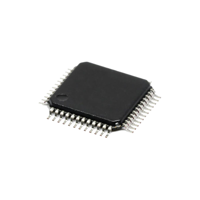
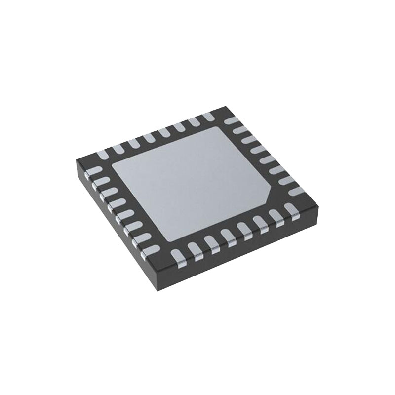
The part is fully specified over the industrial temperature range and is available in an 8-lead narrow SOIC package.
ESD TESTING
Two coupling methods are used for ESD testing, contact discharge and air-gap discharge. Contact discharge calls for a direct connection to the unit being tested. Air-gap discharge uses a higher test voltage but does not make direct contact with the unit under test. With air-gap discharge, the discharge gun is moved toward the unit under test, developing an arc across the air gap, hence the term air-gap discharge. This method is influenced by humidity, temperature, barometric pressure, distance, and rate of closure of the discharge gun. The contact discharge method, while less realistic, is more repeatable and is gaining acceptance and preference over the air-gap method.
Although very little energy is contained within an ESD pulse, the extremely fast rise time, coupled with high voltages, can cause failures in unprotected semiconductors. Catastrophic destruction can occur immediately as a result of arcing or heating. Even if catastrophic failure does not occur immediately, the device can suffer from parametric degradation, which can result in degraded performance. The cumulative effects of continuous exposure can eventually lead to complete failure.
I/O lines are particularly vulnerable to ESD damage. Simply touching or plugging in an I/O cable can result in a static discharge that can damage or completely destroy the interface product connected to the I/O port. It is extremely important, therefore, to have high levels of ESD protection on the I/O lines.
The ESD discharge could induce latch-up in the device under test, so it is important that ESD testing on the I/O pins be carried out while device power is applied. This type of testing is more representative of a real-world I/O discharge, where the equipment is operating normally when the discharge occurs.
DIFFERENTIAL DATA TRANSMISSION
Differential data transmission is used to reliably transmit data at high rates over long distances and through noisy environments. Differential transmission nullifies the effects of ground shifts and noise signals that appear as common-mode voltages on the line.
Two main standards that specify the electrical characteristics of transceivers used in differential data transmission are approved by the Electronics Industries Association (EIA). The RS-422 standard specifies data rates up to 10 Mbps and line lengths up to 4000 feet. A single driver can drive a transmission line with up to 10 receivers. The RS-485 standard was defined to cater to true multipoint communications. This standard meets or exceeds all the requirements of RS-422 but also allows multiple drivers and receivers to be connected to a single bus. An extended common-mode range of −7 V to +12 V is defined.
The most significant difference between RS-422 and RS-485 is the fact that under the RS-485 standard the drivers may be disabled, thereby allowing more than one to be connected to a single line. Only one driver should be enabled at a time, but the RS-485 standard contains additional specifications to guarantee device safety in the event of line contention.


