BESCHREIBUNG
Der LTC7804 ist ein leistungsstarker synchroner DC/DC-Aufwärtsschaltregler, der eine reine N-Kanal-Leistungs-MOSFET-Stufe ansteuert. Die synchrone Gleichrichtung erhöht den Wirkungsgrad, reduziert die Verlustleistung und verringert die thermischen Anforderungen. Eine Current-Mode-Architektur mit konstanter Frequenz ermöglicht eine phasenverriegelbare Schaltfrequenz von bis zu 3MHz. Der LTC7804 arbeitet mit einem weiten Eingangsspannungsbereich von 4,5V bis 40V. Wenn der LTC7804 über den Ausgang des Aufwärtswandlers vorgespannt wird, kann er mit einer Eingangsspannung von nur 1V nach dem Start betrieben werden.
Der sehr niedrige Ruhestrom bei Nulllast verlängert die Betriebszeit in batteriebetriebenen Systemen. Die OPTI-LOOP-Kompensation ermöglicht die Optimierung des Einschwingverhaltens über einen breiten Bereich von Ausgangskapazitäts- und ESR-Werten. Der MODE-Pin wählt zwischen dem Burst-Mode-Betrieb, dem Pulse-Skipping-Modus oder dem kontinuierlichen Induktionsstrommodus bei geringer Last.
Der LTC7804 zeichnet sich außerdem durch einen Spread-Spectrum-Betrieb aus, der die Spitzenwerte des abgestrahlten und leitungsgebundenen Rauschens sowohl auf der Eingangs- als auch auf der Ausgangsseite deutlich reduziert und damit die Einhaltung der Normen für elektromagnetische Störungen (EMI) erleichtert.
FEATURES
Synchroner Betrieb für höchste Effizienz und reduzierte Wärmeabgabe
Großer VIN-Bereich: 4,5V bis 40V und Betrieb bis zu 1V nach dem Einschalten
Ausgangsspannung bis zu 40V
Niedriger Betriebs-IQ: 14μA
Spread Spectrum Betrieb
Pass-Thru™/100% Einschaltdauer-Fähigkeit für Synchron-MOSFET
RSENSE oder Induktor DCR Strommessung
Programmierbare Festfrequenz (100kHz bis 3MHz)
Phasenverriegelbare Frequenz (100kHz bis 3MHz)
Wahlweise kontinuierlicher, Pulse-Skipping- oder Low Ripple Burst Mode®-Betrieb bei geringer Last
Niedrige Abschaltung IQ: 1.2μA
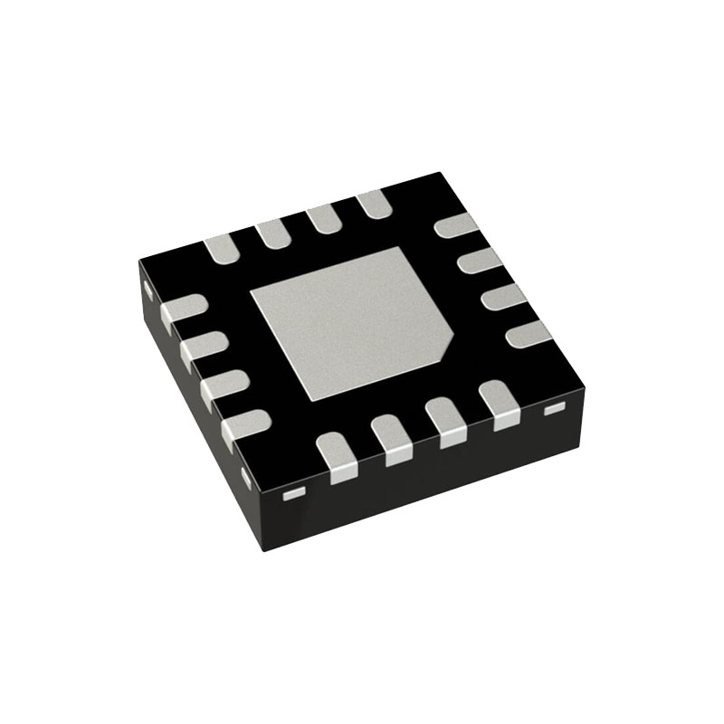
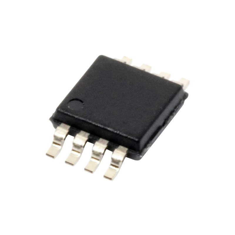
Thermisch optimierte 16-Pin 3mm × 3mm QFN- und MSOP-Gehäuse
AEC-Q100 qualifiziert für Automobilanwendungen
ANWENDUNGEN
Automobil und Transport
Industriell
Militär/Luftfahrtelektronik
Telekommunikation
OPERATION
Hauptkontrollschleife
Der LTC7804 verwendet eine Step-up-Architektur mit konstanter Frequenz und Spitzenstrommodus. Im Normalbetrieb wird der externe untere MOSFET eingeschaltet, wenn der Taktgeber den RS-Latch setzt, und ausgeschaltet, wenn der Hauptstromkomparator ICMP den RS-Latch zurücksetzt. Der Induktionsspitzenstrom, bei dem ICMP auslöst und das Latch zurücksetzt, wird durch die Spannung am ITH-Pin gesteuert, der der Ausgang des Fehlerverstärkers EA ist. Der Fehlerverstärker vergleicht das Ausgangsspannungs-Rückkopplungssignal am VFB-Pin (das mit einem externen Widerstandsteiler erzeugt wird, der über die Ausgangsspannung VOUT mit Masse verbunden ist) mit der internen 1,200V-Referenzspannung. Wenn der Laststrom ansteigt, führt dies zu einer leichten Abnahme von VFB im Verhältnis zur Referenz, was den EA veranlasst, die ITH-Spannung zu erhöhen, bis der durchschnittliche Induktorstrom dem neuen Laststrom entspricht.
Nachdem der untere MOSFET in jedem Zyklus ausgeschaltet wird, wird der obere MOSFET eingeschaltet, bis entweder der Induktorstrom beginnt, sich umzukehren, wie vom Stromkomparator IR angezeigt, oder bis zum Beginn des nächsten Taktzyklus.
Herunterfahren und Hochfahren (RUN, SS Pins)
Der LTC7804 kann über den RUN-Pin abgeschaltet werden. Wenn Sie diesen Pin unter 1,1V ziehen, wird der Hauptregelkreis abgeschaltet. Wenn Sie den RUN-Pin unter 0,7V ziehen, werden der Controller und die meisten internen Schaltungen, einschließlich der INTVCC-LDOs, deaktiviert. In diesem Zustand verbraucht der LTC7804 nur 1,2μA Ruhestrom.
HINWEIS: Belasten Sie den Chip nicht über einen längeren Zeitraum, während er sich im Shutdown befindet. Die oberen MOSFETs werden während des Shutdowns abgeschaltet und die Ausgangslast kann zu einer übermäßigen Verlustleistung in den Body-Dioden führen.
Betrieb mit geringem Laststrom: Burst Mode Betrieb, Pulse-Skipping oder Forced Continuous Mode (MODE Pin)
Der LTC7804 kann bei niedrigen Lastströmen in den hocheffizienten Burst-Modus, den Pulse-Skipping-Modus mit konstanter Frequenz oder den erzwungenen Dauerleitungsmodus versetzt werden.
Um den Burst-Modus zu wählen, verbinden Sie den MODE-Pin mit GND. Um den erzwungenen Dauerbetrieb zu wählen, verbinden Sie den MODE-Pin mit INTVCC. Um den Puls-Skipping-Modus auszuwählen, verbinden Sie den MODE-Pin mit einer Gleichspannung von mehr als 1,2V und weniger als INTVCC - 1,3V. Ein interner 100k-Widerstand gegen GND ruft den Burst-Modus auf, wenn der MODE-Pin potentialfrei ist, und den Puls-Skipping-Modus, wenn der MODE-Pin über einen externen 100k-Widerstand mit INTVCC verbunden ist.

