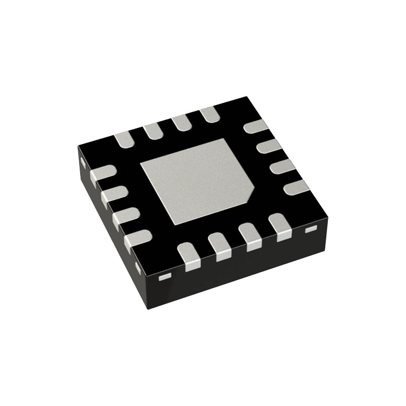
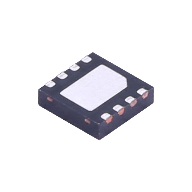
DESCRIPCIÓN
El LTC4211 es un controlador de intercambio en caliente que permite insertar y extraer de forma segura una placa de una placa base activa. Un controlador de interruptor de lado alto interno controla la puerta de un MOSFET de canal N externo para tensiones de alimentación de 2,5 V a 16,5 V. El LTC4211 proporciona un arranque suave y una limitación de la corriente de irrupción durante el periodo de arranque, que tiene una duración programable.
Two on-chip current limit comparators provide dual level overcurrent circuit breaker protection. The slow comparator trips at VCC – 50mV and activates in 20μs (or is programmed by an external filter capacitor, MS only). The fast comparator trips at VCC – 150mV and typically responds in 300ns.
The FB pin monitors the output supply voltage and signals the RESET output pin. The ON pin signal turns the chip on and off and can also be used for the reset function. The MS package has FAULT and FILTER pins to provide additional functions like fault indication, autoretry or latch-off modes, programmable current limit response time and programmable overvoltage protection using an external Zener diode clamp.
CARACTERÍSTICAS
Allows Safe Board Insertion and Removal from a Live Backplane
Controla tensiones de alimentación de 2,5 V a 16,5 V
Arranque suave programable con limitación de la corriente de irrupción, sin condensador de puerta externo
Faster Turn-Off Time Because No External Gate Capacitor is Required
Protección de sobreintensidad de doble nivel
Programmable Response Time for Overcurrent Protection (MS)
Protección de sobretensión programable (MS)
Reintento automático o funcionamiento en modo enclavado (MS)
Accionamiento del lado de alta para un FET externo de canal N
Tensión de alimentación programable por el usuario Velocidad de encendido
El pin FB monitoriza VOUT y señala RESET
Glitch Filter Protects Against Spurious RESET Signal
APLICACIONES
Disyuntor electrónico
Hot Board Insertion and Removal (Either On Backplane or On Removable Card)
Interruptor automático industrial de lado alto
OPERACIÓN
INSERCIÓN DE CIRCUITO CALIENTE
Cuando se insertan o retiran placas de circuitos de placas base activas, los condensadores de derivación de alimentación pueden extraer enormes corrientes transitorias del bus de alimentación de la placa base mientras se cargan. La corriente transitoria puede causar daños permanentes en los pines del conector, así como provocar fallos en la alimentación del sistema, haciendo que otras placas del sistema se reinicien.
El LTC4211 está diseñado para encender y apagar las tensiones de alimentación de una placa de circuito impreso de forma controlada, lo que permite insertar o extraer la placa de circuito impreso de forma segura de una placa base con tensión. El dispositivo proporciona una señal de reinicio del sistema para indicar cuando la tensión de alimentación de la placa cae por debajo de un nivel predeterminado, así como un monitor de fallos de doble función.
MONITOR DE TENSIÓN DE SALIDA
The LTC4211 uses a 1.236V bandgap reference, precision voltage comparator and an external resistive divider to monitor the output supply voltage.
The operation of the supply monitor in normal mode is illustrated in Figure 2. When the voltage at the FB pin drops below its reset threshold (1.236V), the comparator COMP2 output goes high. After a glitch filter delay, RESET is pulled low (Time Point 1). When the voltage at the FB pin rises above its reset threshold (1.239V), COMP2’s output goes low and a timing cycle starts (Time Point 4). After a complete timing cycle, RESET is pulled high by the external pull-up resistor. If the FB pin rises above the reset threshold for less than a timing cycle, the RESET output remains low (Time Points 2 to 3).
The LTC4211’s RESET pin is logic low during any undervoltage lockout condition and during the initial insertion of a PC board. Under normal operation, RESET goes to logic high at the end of the soft-start cycle only after the FB pin voltage rises above its reset threshold of 1.239V.
BLOQUEO POR SUBTENSIÓN
El circuito de reinicio de encendido del LTC4211 inicializa el procedimiento de arranque y garantiza que el chip se encuentre en el estado adecuado si la tensión de alimentación de entrada es demasiado baja. Si la tensión de alimentación cae por debajo de 2,18 V, el LTC4211 entra en modo de bloqueo por subtensión (UVLO) y el pin GATE se pone a nivel bajo. Dado que el circuito UVLO utiliza histéresis, el chip se reinicia cuando la tensión de alimentación sube por encima de 2,3 V y la patilla ON se pone a nivel alto.
In addition, users can utilize the ON comparator (COMP1) or the FAULT comparator (COMP6) to effectively program a higher undervoltage lockout level. Figure 3 shows how the external resistive divider at the ON pin programs the system’s undervoltage lockout voltage. The system will enter the plug-in cycle after the ON pin rises above 1.316V. The resistive divider sets the circuit to turn on when VCC reaches around 79% of its final value. If a different turn on VCC voltage is desired change the resistive divider values accordingly. Alternatively, the FAULT comparator can be used to configure the external undervoltage lockout level. If the FAULT comparator is used for this purpose, the system will wait for the input voltage to increase above the level set by the user before starting the second timing cycle. Also, if the input voltage drops below the set level in normal operating mode, the user must cycle the ON pin or VCC to restart the system.

