Descripción
The AT24C01C/AT24C02C provides 1,024/2,048 bits of Serial Electrically Erasable and Programmable Read-Only Memory (EEPROM) organized as 128/256 words of 8 bits each. The device’s cascading feature allows up to eight devices to share a common two‑wire bus. This device is optimized for use in many industrial and commercial applications where low-power and low-voltage operations are essential.
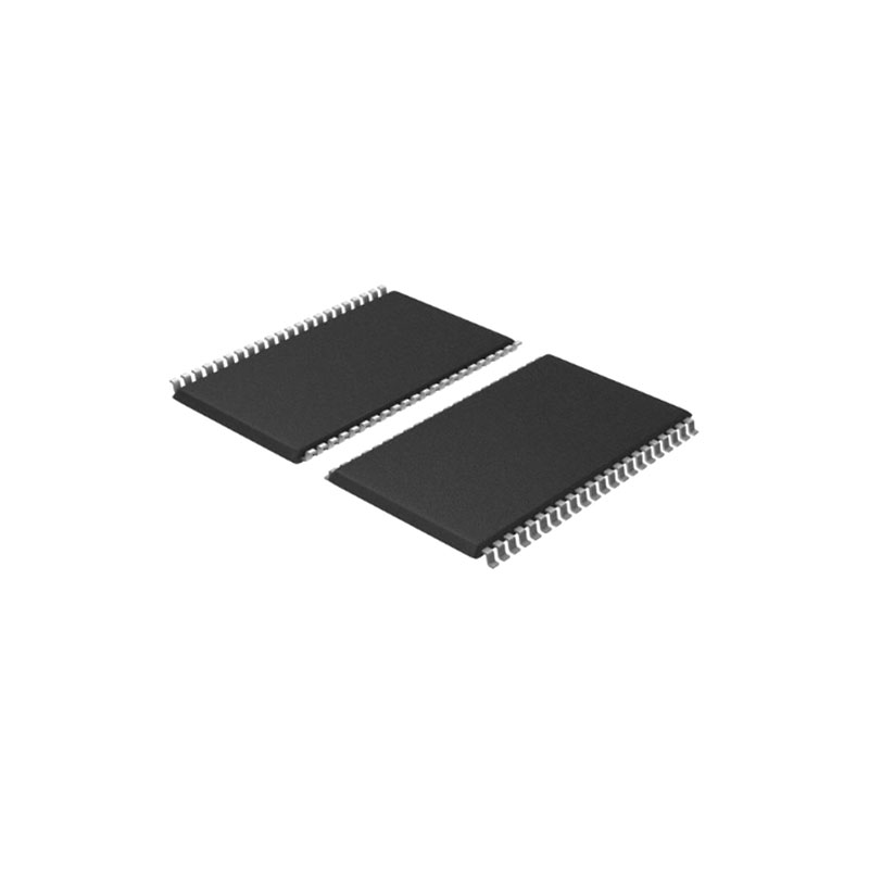
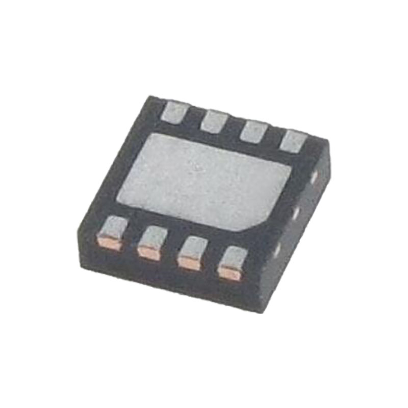
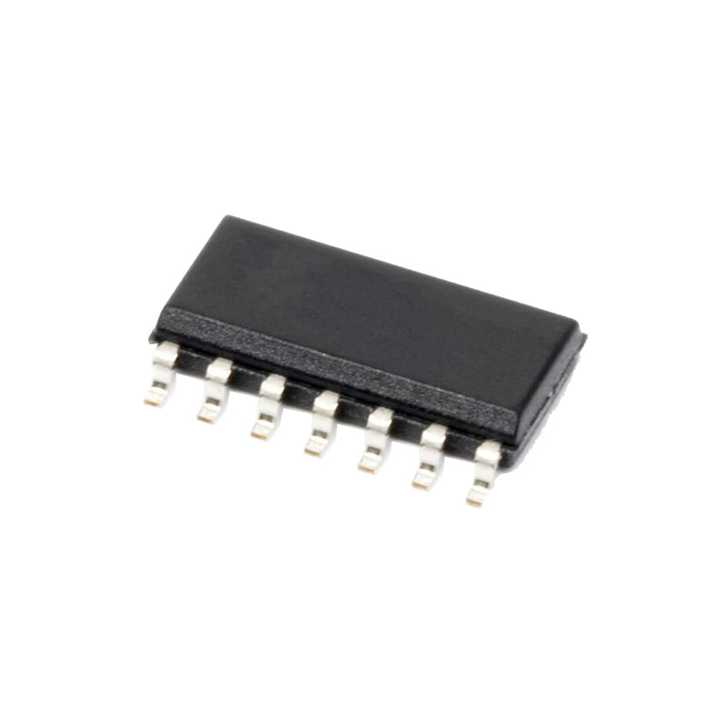
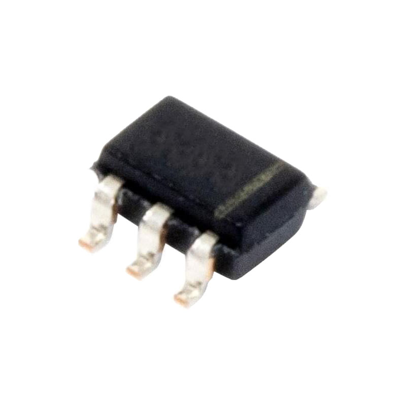
The device is available in space-saving 8-lead SOIC, 8-lead TSSOP, 8-pad UDFN, 8-lead PDIP, 5-lead SOT23 and 8-ball VFBGA packages. All packages operate from 1.7V to 5.5V.
Características
• Low-Voltage Operation:
- VCC = 1,7 V a 5,5 V
• Internally Organized as 128 x 8 (1K) or 256 x 8 (2K)
- Temperatura industrial: -40°C a +85°C
- Interfaz serie compatible con I2C (dos hilos):
- 100 kHz Modo estándar, 1,7 V a 5,5 V
- 400 kHz Modo rápido, 1,7 V a 5,5 V
- Modo rápido Plus (FM+) de 1 MHz, de 2,5 V a 5,5 V
- Disparadores Schmitt, entradas filtradas para supresión de ruido
- Protocolo de transferencia bidireccional de datos
- Clavija de protección contra escritura para la protección completa de datos por hardware de la matriz
- Corriente activa ultrabaja (3 mA máximo) y corriente de espera (6 μA máximo)
• 8-Byte Page Write Mode:
- Se permiten escrituras parciales de páginas
- Modos de lectura aleatoria y secuencial
- Ciclo de escritura automático en 5 ms como máximo
• ESD Protection > 4,000V
- Alta fiabilidad:
- Resistencia: 1.000.000 de ciclos de escritura
- Conservación de datos: 100 años
- Opciones de embalaje ecológico (sin plomo, sin haluro y conforme a la directiva RoHS)
- Opciones de venta de troqueles: Forma de oblea y obleas con protuberancias
Entradas de dirección de dispositivo (A0, A1, A2)
Los pines A0, A1 y A2 son entradas de dirección de dispositivo que están cableadas (directamente a GND o a VCC) para compatibilidad con otros dispositivos EEPROM serie de dos hilos. Cuando los pines están cableados, se pueden direccionar hasta ocho dispositivos en un único sistema de bus. Un dispositivo se selecciona cuando el hardware y el software coinciden. Si estos pines se dejan flotando, los pines A0, A1 y A2 se bajarán internamente a GND. Sin embargo, debido al acoplamiento capacitivo que puede aparecer en las aplicaciones del cliente, Microchip recomienda conectar siempre los pines de dirección a un estado conocido. Cuando utilice una resistencia de pull-up, Microchip recomienda utilizar 10 kΩ o menos.
Serial Data (SDA)
The SDA pin is an open-drain bidirectional input/output pin used to serially transfer data to and from the device. The SDA pin must be pulled high using an external pull-up resistor (not to exceed 10 kΩ in value) and may be wire-ORed with any number of other open-drain or open-collector pins from other devices on the same bus.
Serial Clock (SCL)
The SCL pin is used to provide a clock to the device and to control the flow of data to and from the device. Command and input data present on the SDA pin is always latched in on the rising edge of SCL, while output data on the SDA pin is clocked out on the falling edge of SCL. The SCL pin must either be forced high when the serial bus is idle or pulled high using an external pull-up resistor.
Write-Protect (WP)
The write-protect input, when connected to GND, allows normal write operations. When the WP pin is connected directly to VCC, all write operations to the protected memory are inhibited.
If the pin is left floating, the WP pin will be internally pulled down to GND. However, due to capacitive coupling that may appear in customer applications, Microchip recommends always connecting the WP pin to a known state. When using a pull‑up resistor, Microchip recommends using 10 kΩ or less.
Device Reset
To prevent inadvertent write operations or any other spurious events from occurring during a power-up sequence, the AT24C01C/AT24C02C includes a Power-on Reset (POR) circuit. Upon power-up, the device will not respond to any commands until the VCC level crosses the internal voltage threshold (VPOR) that brings the device out of Reset and into Standby mode.