Descripción
El LTC4001 es un cargador de baterías Li-Ion de 2A destinado a adaptadores de pared de 5V. Utiliza una topología de convertidor Buck síncrono de 1,5 MHz para reducir la disipación de potencia durante la carga. La baja disipación de potencia, un MOSFET interno y la resistencia de detección permiten un cargador físicamente pequeño que puede ser integrado en una amplia gama de aplicaciones portátiles. El LTC4001 incluye circuitos completos de terminación de carga, recarga automática y una tensión de flotación de ±1% 4,2V. Se incluye protección contra cortocircuitos de entrada, por lo que no se requiere diodo de bloqueo.
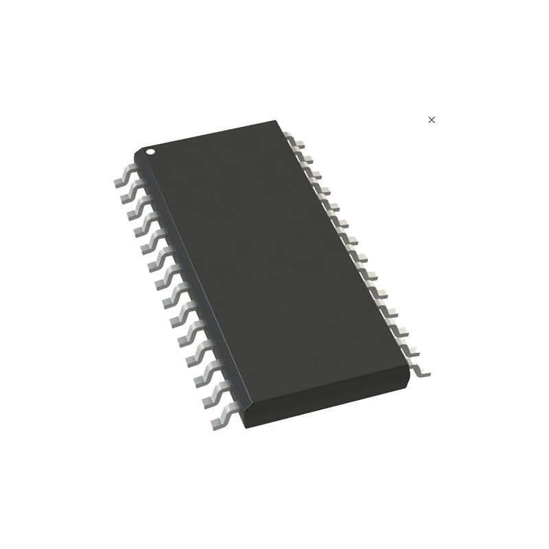
Los parámetros de corriente de carga de la batería, tiempo de espera de carga e indicación de fin de carga se ajustan con componentes externos. Otras funciones son la detección de celdas en cortocircuito, la carga en función de la temperatura y la protección contra sobretensiones. El LTC4001 está disponible en un encapsulado QFN de 16 terminales (4 mm × 4 mm) y bajo perfil (0,75 mm).
CARACTERÍSTICAS
Baja disipación de energía
2A Corriente de carga máxima
No se necesitan MOSFET externos, resistencia de detección ni diodo de bloqueo
Teledetección en los bornes de la batería
Temporizador de terminación de carga programable
Tensión de flotación preestablecida de 4,2 V con una precisión de ±0,5%
Detección/Terminación de corriente de carga programable
Recarga automática
Entrada de termistor para carga en función de la temperatura
Compatible con los adaptadores de pared limitados actuales
Encapsulado QFN de bajo perfil de 16 terminales (4 mm × 4 mm)
Aplicaciones
Dispositivos portátiles a pilas
Ordenadores de mano
Bases de carga
Cámaras digitales
Teléfonos inteligentes
Operación
El LTC4001 es un cargador de baterías Li-Ion de corriente constante y tensión constante basado en una arquitectura buck síncrona. La baja disipación de potencia hace práctica la carga continua de la batería a alta velocidad (2A). La corriente continua de carga de la batería se programa mediante una resistencia RPROG (o una corriente de salida DAC) en el pin PROG. El voltaje final de flotación de la batería se ajusta internamente a 4,2V.
Protección contra sobretensión, sobretemperatura del chip y corriente de cortocircuito
El LTC4001 incluye sobretensión, sobretemperatura del chip y varias variedades de protección contra cortocircuitos.
Un comparador apaga ambos cargadores (alta velocidad y goteo) si el voltaje de la batería excede el voltaje de flotación en aproximadamente 5%. Esto puede ocurrir en situaciones en las que la batería se desconecta accidentalmente mientras se está cargando.
Un comparador controla continuamente la temperatura en el chip y apagará el cargador de batería cuando la temperatura del chip supere los 160°C aproximadamente. La carga de la batería se activará de nuevo cuando la temperatura descienda a aproximadamente 150°C.
La protección contra cortocircuitos se proporciona de varias maneras diferentes. Primero, un cortocircuito fuerte en los terminales de la batería hará que la carga entre en modo de carga lenta, limitando la corriente de carga a la corriente de carga lenta (típicamente 50mA). En segundo lugar, se evita la carga PWM si la corriente de carga de alta velocidad se programa muy por encima de la corriente de carga máxima recomendada de 2A (a través del pin PROG). Tercero, un comparador de sobrecorriente monitoriza el pico de corriente del inductor.
INFORMACIÓN SOBRE APLICACIONES
Arranque suave y selección del condensador de compensación
El LTC4001 tiene un cargador de baja corriente y un cargador de alta corriente basado en PWM. El arranque suave se utiliza siempre que el cargador de alta tasa se enciende inicialmente, evitando una alta corriente de arranque. La velocidad de rampa de arranque suave se ajusta mediante la corriente de pull-up interna de 12,8µA y un condensador externo. El rango de control en el pin SS es de aproximadamente 0.3V a 1.6V. Con un condensador de 0,1µF, el tiempo de rampa hasta el ciclo de trabajo máximo es de aproximadamente 10 ms.
El condensador externo en la patilla SS también establece la compensación para el bucle de control de corriente y el bucle de control de tensión de flotación. Se requiere una capacitancia mínima de 10nF.
Condensadores de entrada y salida
El LTC4001 utiliza un regulador buck síncrono para proporcionar una alta corriente de carga de la batería. Se recomienda un condensador cerámico de chip de 10µF para los condensadores de entrada y salida, ya que proporciona una ESR y ESL bajas y puede manejar las altas corrientes de rizado RMS. Sin embargo, algunos condensadores de alto Q pueden producir transitorios elevados debido a la auto-resonancia en algunas condiciones de arranque, como la conexión de la entrada del cargador a una fuente de alimentación caliente. Para más información, consulte la Nota de aplicación 88.
Las consideraciones EMI normalmente hacen que sea deseable minimizar la corriente de rizado en los cables de la batería, y se pueden añadir perlas o inductores para aumentar la impedancia de la batería a la frecuencia de conmutación de 1,5MHz. La corriente de ondulación de conmutación se divide entre la batería y el condensador de salida dependiendo de la ESR del condensador de salida y de la impedancia de la batería. Si la ESR del condensador de salida es de 0,1Ω y la impedancia de la batería se eleva a 2Ω con una perla o inductor, sólo 5% de la corriente de rizado fluirá en la batería. Técnicas similares también se pueden aplicar para minimizar la EMI de los cables de entrada.