DESCRIPCIÓN GENERAL
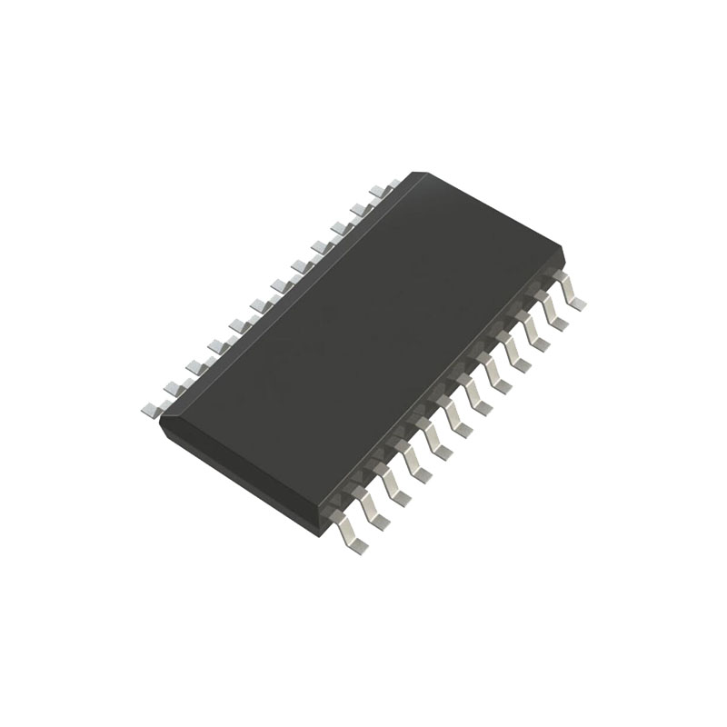
El ADE7758 es un CI de medida de energía eléctrica trifásica de alta precisión con una interfaz serie y dos salidas de pulsos. El ADE7758 incorpora ADCs Σ-Δ de segundo orden, un integrador digital, circuitería de referencia, un sensor de temperatura y todo el procesado de señal necesario para realizar medidas de energía activa, reactiva y aparente y cálculos rms. El ADE7758 es adecuado para medir la energía activa, reactiva y aparente en varias configuraciones trifásicas, como servicios WYE o DELTA, con tres y cuatro hilos. El ADE7758 proporciona funciones de calibración del sistema para cada fase, es decir, corrección de offset rms, calibración de fase y calibración de potencia. La salida lógica APCF proporciona información de potencia activa, y la salida lógica VARCF proporciona información instantánea de potencia reactiva o aparente.El ADE7758 tiene un registro de muestreo de forma de onda que permite el acceso a las salidas del ADC. La pieza también incorpora un circuito de detección de variaciones de baja o alta tensión de corta duración. Los niveles de umbral de tensión y la duración (número de ciclos de media línea) de la variación son programables por el usuario. La detección del paso por cero se sincroniza con el punto de paso por cero de la tensión de línea de cualquiera de las tres fases. Esta información puede utilizarse para medir el periodo de cualquiera de las tres entradas de tensión. La detección del cruce por cero se utiliza dentro del chip para el modo de acumulación de energía del ciclo de línea. Este modo permite una calibración más rápida y precisa sincronizando la acumulación de energía con un número entero de ciclos de línea. Los datos se leen desde el ADE7758 a través de la interfaz serie SPI. La salida de solicitud de interrupción (IRQ) es una salida lógica de drenaje abierto, activa baja. La salida IRQ se activa cuando se producen una o más interrupciones en el ADE7758. Un registro de estado indica la naturaleza de la interrupción. El ADE7758 se presenta en un encapsulado SOIC de 24 terminales.
CARACTERÍSTICAS
Alta precisión; compatible con IEC 60687, IEC 61036, IEC 61268, IEC 62053-21, IEC 62053-22 e IEC 62053-23
Compatible con servicios trifásicos/3 hilos, trifásicos/4 hilos y otros servicios trifásicos
Error de energía activa inferior a 0,1% en un rango dinámico de 1000 a 1 a 25°C
Suministra datos de energía activa/reactiva/aparente, tensión eficaz, corriente eficaz y forma de onda muestreada.
Dos salidas de impulsos, una para potencia activa y otra seleccionable entre potencia reactiva y aparente con frecuencia programable
Calibración digital de potencia, fase y offset rms
Umbrales en chip programables por el usuario para detecciones de sobretensión y SAG de tensión de línea
Un integrador digital en chip permite una interfaz directa con sensores de corriente con salida di/dt
Un PGA en el canal de corriente permite una interfaz directa con los transformadores de corriente
Una interfaz serie compatible con SPI con IRQ Los ADC y DSP patentados proporcionan una gran precisión frente a grandes variaciones en las condiciones ambientales y el tiempo
Referencia 2,4 V (deriva 30 ppm/°C típica) con capacidad de sobrecarga externa
Alimentación única de 5 V, bajo consumo (70 mW típico)
TEORÍA DE FUNCIONAMIENTO
FILTRO ANTIALIASING
Este filtro evita el aliasing, que es un artefacto de todos los sistemas muestreados. Las señales de entrada con componentes de frecuencia superiores a la mitad de la frecuencia de muestreo del ADC distorsionan la señal muestreada a una frecuencia inferior a la mitad de la frecuencia de muestreo. Esto ocurre con todos los ADC, independientemente de su arquitectura. La combinación de la alta velocidad de muestreo ∑-Δ ADC utilizada en el ADE7758 con el ancho de banda relativamente bajo del medidor de energía permite utilizar un filtro de paso bajo (LPF) muy simple como filtro antialiasing. Un simple filtro RC (un solo polo) con una frecuencia de esquina de 10 kHz produce una atenuación de aproximadamente 40 dB a 833 kHz. Esto suele ser suficiente para eliminar los efectos del aliasing.
ENTRADAS ANALÓGICAS
El ADE7758 dispone de seis entradas analógicas divididas en dos canales: corriente y tensión. El canal de corriente consta de tres pares de entradas de tensión totalmente diferenciales: IAP e IAN, IBP e IBN, e ICP e ICN. Estos pares de entradas de tensión totalmente diferenciales tienen una señal diferencial máxima de ±0,5 V. El canal de corriente dispone de un amplificador de ganancia programable (PGA) con selección de ganancia posible de 1, 2 ó 4. Además del PGA, los canales de corriente también tienen una selección de rango de entrada de escala completa para el ADC. La selección del rango de entrada analógica del ADC también se realiza mediante el registro de ganancia (véase la Figura 38). Como se ha mencionado anteriormente, la tensión de entrada diferencial máxima es de ±0,5 V. Sin embargo, utilizando el Bit 3 y el Bit 4 del registro de ganancia, la tensión de entrada máxima del ADC puede ajustarse a ±0,5 V, ±0,25 V o ±0,125 V en los canales de corriente. Esto se consigue ajustando la referencia del ADC (véase la sección Circuito de referencia).


