DESCRIPCIÓN GENERAL
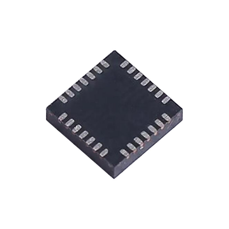
El ADMV1013 es un upconverter de microondas de banda ancha optimizado para diseños de radio de microondas punto a punto que operan en el rango de radiofrecuencia (RF) de 24 GHz a 44 GHz. El Upconverter ofrece dos modos de conversión de frecuencia. El dispositivo es capaz de realizar la conversión directa a RF a partir de señales de entrada en cuadratura en fase (I/Q) de banda base, así como la conversión ascendente a banda lateral única (SSB) a partir de entradas complejas de frecuencia intermedia (FI). La ruta de entrada I/Q de banda base puede desactivarse y las señales complejas de FI moduladas, desde 0,8 GHz a 6,0 GHz, pueden insertarse en la ruta de FI y convertirse a 24 GHz a 44 GHz, suprimiendo al mismo tiempo la banda lateral no deseada, normalmente mejor que 26 dBc. La interfaz de puerto serie (SPI) permite ajustar la fase de cuadratura y la tensión de puerta del mezclador para conseguir una supresión óptima de la banda lateral y la anulación del oscilador local (LO). Además, la interfaz SPI permite apagar el detector de envolvente de salida para reducir el consumo de energía. El upconverter ADMV1013 se presenta en un encapsulado LGA de 40 terminales. El ADMV1013 funciona en un rango de temperatura de -40°C a +85°C.
CARACTERÍSTICAS
Gama de frecuencias de entrada de RF de banda ancha: de 24 GHz a 44 GHz
2 modos de conversión ascendente Conversión directa de banda base I/Q a RF Conversión ascendente de banda lateral única a partir de FI real
Gama de frecuencias de entrada LO: 5,4 GHz a 10,25 GHz
Cuádruple LO hasta 41 GHz
Entradas de FI y salida de RF de un solo extremo de 50 Ω adaptadas
Opción entre 100 Ω simétricos balanceados o 50 Ω simples
entradas LO terminadas
Entradas de banda base balanceadas de 100 Ω
Supresión de banda lateral y optimización del paso de portadora
Atenuador variable para controlar la potencia del transceptor
Programable mediante interfaz SPI de 4 hilos
Paquete LGA de 40 terminales
APLICACIONES
Radios de microondas punto a punto
Radar, sistemas de guerra electrónica
Instrumentación, equipos de prueba automáticos (ATE)
TEORÍA DE FUNCIONAMIENTO
El ADMV1013 es un convertidor ascendente de microondas de banda ancha optimizado para diseños de radio de microondas que operan en el rango de frecuencias de RF de 24 GHz a 44 GHz. Consulte la Figura 1 para ver un diagrama de bloques funcional del dispositivo. Los ajustes digitales del ADMV1013 se controlan a través del SPI. El ADMV1013 tiene dos modos de funcionamiento:
- Modulación en cuadratura de banda base (modo I/Q)
- Conversión ascendente de banda lateral única (modo FI)
SECUENCIA DE ARRANQUE
Para utilizar el control de tensión RF VVA1 y RF VVA2, la alimentación VCC_VVA (1,8 V) debe estar activada. Las patillas VCTRL1 y VCTRL2 controlan la ganancia de RF VVA1 y RF VVA2. Del mismo modo, para utilizar el control SPI, es necesario encender primero DVDD y luego realizar un hard reset conmutando el pin RST a lógica baja y luego a lógica alta. Los ajustes SPI del ADMV1013 requieren que los ajustes por defecto se cambien durante el arranque para un rendimiento óptimo. Ajuste el Registro 0x0A a 0xE700 después de cada encendido o reinicio. MODULACIÓN DE CUADRATURA DE BANDA BASE (MODO I/Q) En el modo I/Q, la impedancia de entrada de los pines de banda base (I_P, I_N, Q_P, y Q_N) son 100 Ω diferencial. Estas entradas se pueden cargar con una carga diferencial de 100 Ω acoplada en cc. I_P e I_N son las entradas I de banda base diferencial, y Q_P y Q_N son las entradas Q de banda base diferencial. Estas entradas pueden operar desde un VCM de 0 V a 2,6 V. Los puertos I/Q de banda base pueden operar desde dc a 6,0 GHz en cada canal I y Q. Para configurar el ADMV1013 en modo I/Q, ajuste el bit MIXER_IF_EN (Registro 0x03, Bit 7) a 0. Al cambiar el VCM externo, también debe cambiarse la tensión de puerta del mezclador interno. Para realizar este cambio, ajuste los bits MIXER_VGATE (Registro 0x05, Bits[6:0]). El valor de MIXER_VGATE sigue al VCM de forma que, para un VCM de 0 V a 1,8 V, MIXER_VGATE = 23,89 VCM + 81, y para un VCM >1,8 V a 2,6 V, MIXER_VGATE = 23,75 VCM + 1,25.
CONVERSIÓN ASCENDENTE DE BANDA LATERAL ÚNICA (SI MODO)
El ADMV1013 tiene la capacidad de convertir una entrada de FI real en cualquier punto entre 0,8 GHz y 6,0 GHz, a la vez que suprime la banda lateral no deseada con un valor superior a 26 dBc. Las entradas de FI son en cuadratura entre sí, 50 Ω single ended, y están internamente acopladas en cc. IF_I e IF_Q son las entradas de FI en cuadratura. Se requiere un híbrido externo de 90° para seleccionar la banda lateral apropiada. Para configurar el ADMV1013 en modo FI, ajuste el bit MIXER_IF_EN (Registro 0x03, Bit 7) a 1. El bit MIXER_IF_EN se pone por defecto en modo FI al arrancar y reiniciar el SPI. Además, los pines de banda base (I_P, I_N, Q_P, y Q_N) deben ver una carga abierta para un rendimiento óptimo en modo FI.


