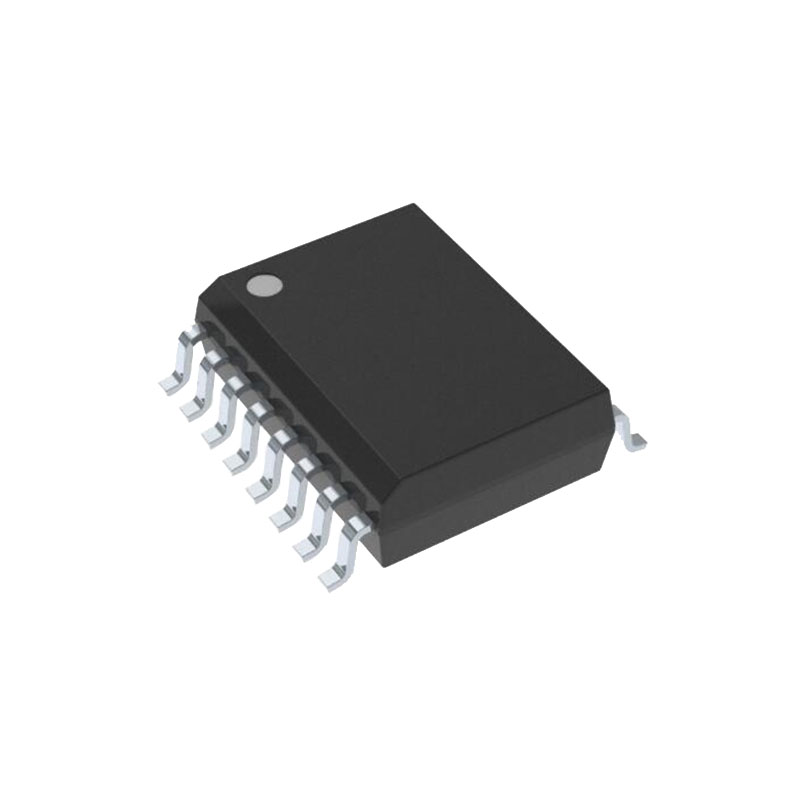
Descripción
El dispositivo DRV8870 es un controlador de motor de CC con escobillas para impresoras, electrodomésticos, equipos industriales y otras máquinas pequeñas. Dos entradas lógicas controlan el controlador Hbridge, que consta de cuatro MOSFET de canal N que pueden controlar motores bidireccionalmente con una corriente de pico de hasta 3,6 A. Las entradas pueden ser moduladas por ancho de pulsos (PWM) para controlar la velocidad del motor, utilizando una selección de modos de caída de corriente. Si se ponen ambas entradas a nivel bajo, se entra en un modo de reposo de bajo consumo.
El dispositivo DRV8870 dispone de regulación de corriente integrada, basada en la entrada analógica VREF y la tensión de la patilla ISEN, que es proporcional a la corriente del motor a través de una resistencia sensora externa. La capacidad de limitar la corriente a un nivel conocido puede reducir significativamente los requisitos de potencia del sistema y la capacitancia necesaria para mantener una tensión estable, especialmente en condiciones de arranque y parada del motor.
El dispositivo está totalmente protegido contra fallos y cortocircuitos, incluidos subvoltaje (UVLO), sobrecorriente (OCP) y sobretemperatura (TSD). Cuando se elimina la condición de fallo, el dispositivo reanuda automáticamente el funcionamiento normal.
Características
- Controlador de motor de puente en H
- Acciona un motor de CC, un devanado de un motor paso a paso u otras cargas
- Tensión de funcionamiento de 6,5 V a 45 V
- 565-mΩ RDS(on) típica (HS + LS)
- Accionamiento de corriente de pico de 3,6 A
- Interfaz de control PWMC
- Regulación de corriente integrada
- Modo de reposo de bajo consumo
- Dimensiones y tamaño reducidos
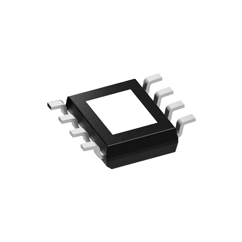
- HSOP de 8 patillas con PowerPAD™.
- 4,9 × 6,0 mm
- Funciones de protección integradas
- VMBloqueo de subtensión (UVLO)
- Protección contra sobrecorriente (OCP)
- Apagado térmico (TSD)
- Recuperación automática de fallos
Aplicaciones
- Impresoras
- Electrodomésticos
- Equipamiento industrial
- Otras aplicaciones mecatrónicas
Visión general
El dispositivo DRV8870 es un dispositivo optimizado de 8 patillas para accionar motores de CC con escobillas de 6,5 a 45 V y hasta 3,6 A de corriente de pico. La regulación de corriente integrada restringe la corriente del motor a un máximo predefinido. Dos entradas lógicas controlan el driver de puente en H, que consta de cuatro MOSFET de canal N que tienen un Rds(on) típico de 565 mΩ (incluyendo un FET de lado alto y otro de lado bajo). Una entrada de alimentación única, VM, sirve tanto de alimentación del dispositivo como de tensión de polarización del bobinado del motor. La bomba de carga integrada del dispositivo potencia VM internamente y mejora por completo los FET de lado alto. La velocidad del motor puede controlarse con modulación por ancho de pulsos, a frecuencias entre 0 y 100 kHz. El dispositivo dispone de un modo de reposo integrado al que se accede poniendo ambas entradas a nivel bajo. Una serie de características de protección evitan que el dispositivo se dañe si se produce un fallo en el sistema.
Control de puentes
Las entradas pueden ajustarse a tensiones estáticas para el accionamiento del ciclo de trabajo 100%, o pueden ser moduladas por ancho de pulsos (PWM) para velocidad variable del motor. Cuando se utiliza PWM, la conmutación entre accionamiento y frenado suele funcionar mejor. Por ejemplo, para conducir un motor hacia adelante con 50% de las RPM máximas, IN1 = 1 e IN2 = 0 durante el periodo de conducción, e IN1 = 1 e IN2 = 1 durante el otro periodo. Alternativamente, también está disponible el modo de inercia (IN1 = 0, IN2 = 0) para un rápido decaimiento de la corriente. Los pines de entrada se pueden alimentar antes de aplicar VM.
Tiempo muerto
Cuando una salida pasa de alta a baja, o de baja a alta, se introduce automáticamente un tiempo muerto para evitar que se dispare. El tMUERTO tiempo es el tiempo en el medio cuando la salida es High-Z. Si el pin de salida se mide durante tMUERTOla tensión depende de la dirección de la corriente. Si la corriente sale de la patilla, la tensión es una caída de diodo por debajo de tierra. Si la corriente entra en la patilla, la tensión es una caída del diodo por encima de VM. Este diodo es el diodo de cuerpo del FET de lado alto o bajo.
Resistencia de detección
La potencia disipada por la resistencia sensora es igual a IRMS2 × R. Por ejemplo, si la corriente pico del motor es de 3 A, la corriente RMS del motor es de 1,5 A y se utiliza una resistencia sensora de 0,2-Ω, la resistencia disipa 1,5 A2 × 0,2 Ω = 0,45 W. La potencia aumenta rápidamente con niveles de corriente más altos.
Las resistencias suelen tener una potencia nominal dentro de un cierto rango de temperatura ambiente, junto con una curva de potencia reducida para temperaturas ambiente elevadas. Cuando una placa de circuito impreso se comparte con otros componentes que generan calor, el diseñador del sistema debe añadir un margen. Siempre es mejor medir la temperatura real de la resistencia sensora en el sistema final.
Dado que las resistencias de potencia son mayores y más caras que las resistencias estándar, es habitual utilizar varias resistencias estándar en paralelo, entre el nodo de detección y tierra, y distribuir la corriente y la disipación de calor.

