DESCRIPCIÓN
Los LT3756, LT3756-1 y LT3756-2 son controladores CC/CC diseñados para funcionar como fuente de corriente constante para alimentar LEDs de alta corriente. Controlan un MOSFET de potencia de canal N externo de lado bajo a partir de una alimentación interna regulada de 7,15 V. La arquitectura de frecuencia fija y modo de corriente permite un funcionamiento estable en una amplia gama de tensiones de alimentación y salida. Una patilla FB de tensión referenciada a tierra sirve de entrada para varias funciones de protección de LED, y también permite que el convertidor funcione como una fuente de tensión constante. Una patilla de ajuste de frecuencia permite al usuario programar la frecuencia de 100 kHz a 1 MHz para optimizar la eficiencia, el rendimiento o el tamaño de los componentes externos.
Los LT3756/LT3756-1/LT3756-2 detectan la corriente de salida en el lado alto de la cadena de LEDs. La detección de corriente en el lado de alta es el esquema más flexible para la conducción de LEDs, permitiendo la configuración en modo boost, buck o buck-boost. La entrada PWM proporciona relaciones de atenuación de LED de hasta 3000:1, y la entrada CTRL proporciona capacidad de atenuación analógica adicional.
CARACTERÍSTICAS
3000:1 Color verdadero PWM™ Atenuación
Amplio rango de tensión de entrada: 6V a 100V
Tensión de salida de hasta 100 V
Regulación de corriente y tensión constantes
100mV Detección de corriente en el lado alto
Acciona los LED en modo Boost, Buck, Buck-Boost, SEPIC o Flyback
Frecuencia ajustable: de 100 kHz a 1 MHz
Protección LED abierta
Bloqueo de subtensión programable con histéresis
Pin de estado LED abierto mejorado (LT3756-2)
Sincronización de Frecuencia (LT3756-1)
Controlador del interruptor de desconexión PWM
La clavija CTRL proporciona atenuación analógica
Baja corriente de apagado: <1µA
Arranque progresivo programable
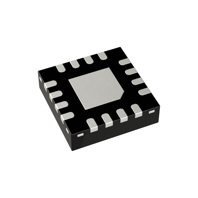
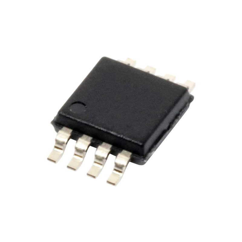
Encapsulados MSOP y QFN de 16 terminales (3 mm × 3 mm) térmicamente mejorados
Cualificación AEC-Q100 para aplicaciones de automoción
APLICACIONES
Aplicaciones LED de alta potencia
Aplicaciones de tensión constante con limitación de corriente
Carga de la batería
OPERACIÓN
El LT3756 es un controlador de modo de corriente de frecuencia constante con un controlador de puerta NMOS de lado bajo. Los drivers de los pines GATE y PWMOUT, y otras cargas del chip, se alimentan desde INTVCC, que es una fuente regulada internamente. En la discusión que sigue, será útil referirse al Diagrama de Bloques del CI. En funcionamiento normal, con el pin PWM bajo, los pines GATE y PWMOUT se conducen a GND, el pin VC es de alta impedancia para almacenar el estado de conmutación anterior en el condensador de compensación externo, y las corrientes de polarización de los pines ISP e ISN se reducen a niveles de fuga. Cuando la patilla PWM pasa a alta, la patilla PWMOUT pasa a alta tras un breve retardo. Al mismo tiempo, el oscilador interno se despierta y genera un impulso para activar el enclavamiento PWM, encendiendo el interruptor MOSFET de potencia externo (GATE pasa a nivel alto). Una entrada de tensión proporcional a la corriente del interruptor, detectada por una resistencia de detección de corriente externa entre los pines de entrada SENSE y GND, se añade a una rampa de compensación de pendiente estabilizadora y la señal resultante de "detección de corriente del interruptor" se introduce en el terminal positivo del comparador PWM. La corriente en el inductor externo aumenta constantemente durante el tiempo que el interruptor está encendido. Cuando la tensión de detección de corriente del interruptor supera la salida del amplificador de error, etiquetado como "VC", el enclavamiento se restablece y el interruptor se apaga. Durante la fase de apagado, la corriente del inductor disminuye. Al finalizar cada ciclo del oscilador, las señales internas, como la compensación de pendiente, vuelven a sus puntos de partida y comienza un nuevo ciclo con el impulso establecido del oscilador.
INFORMACIÓN SOBRE APLICACIONES
Control de atenuación
Hay dos métodos para controlar la fuente de corriente para la atenuación utilizando el LT3756. Un método utiliza el pin CTRL para ajustar la corriente regulada en los LEDs. Un segundo método utiliza el pin PWM para modular la fuente de corriente entre cero y toda la corriente para lograr una corriente media programada con precisión. Para que la regulación PWM sea más precisa, la corriente de demanda del interruptor se almacena en el nodo VC durante la fase de reposo cuando PWM está bajo. Esta característica minimiza el tiempo de recuperación cuando la señal PWM pasa a alta. Para mejorar aún más el tiempo de recuperación, se puede utilizar un interruptor de desconexión en la ruta de corriente del LED para evitar que el nodo ISP se descargue durante la fase baja de la señal PWM. El tiempo mínimo de activación o desactivación del PWM dependerá de la elección de la frecuencia de funcionamiento y de la selección de componentes externos. Con el funcionamiento en modo de conducción discontinua (DCM), se pueden conseguir pulsos de corriente regulada tan cortos como 1µs. Pero, la mejor combinación global de PWM y regulación analógica (con CTRL) está disponible si el pulso PWM mínimo es de al menos seis ciclos de conmutación.


