DESCRIPCIÓN
Los LTC3545/LTC3545-1 son reguladores buck síncronos monolíticos triples de alta eficiencia que utilizan una arquitectura de frecuencia constante y modo de corriente. Los reguladores funcionan de forma independiente con patillas de ejecución separadas. El rango de tensión de entrada de 2,25 V a 5,5 V hace que el LTC3545/LTC3545-1 sea muy adecuado para aplicaciones alimentadas con una sola batería de iones de litio. Se puede seleccionar externamente el modo de salto de pulsos de bajo rizado o el modo de ráfaga de alta eficiencia. El funcionamiento en modo de salto de pulsos PWM proporciona una tensión de rizado de salida muy baja, mientras que el funcionamiento en modo ráfaga aumenta la eficiencia con cargas de salida bajas.
La frecuencia de conmutación se ajusta internamente a 2,25 MHz, o puede sincronizarse con un reloj externo de 1 MHz a 3 MHz. Los indicadores de buen estado de la alimentación permiten secuenciar fácilmente el encendido entre los tres reguladores.
Los conmutadores síncronos internos aumentan la eficiencia y eliminan los diodos Schottky externos. Las bajas tensiones de salida se soportan con la tensión de referencia de realimentación de 0,6 V.
CARACTERÍSTICAS
Tres salidas de 800 mA
Alta eficiencia: Hasta 95%
2,25 V a 5,5 V Rango de tensión de entrada
Baja ondulación (<20mVP-P) Funcionamiento en modo ráfaga IQ: 58μA
Funcionamiento a frecuencia constante de 2,25 MHz o
Sincronizable con reloj externo de 1MHz a 3MHz
Indicadores de buena alimentación Facilitan la secuenciación del suministro
La referencia de 0,6 V permite tensiones de salida bajas
Funcionamiento en modo corriente/Excelente respuesta transitoria
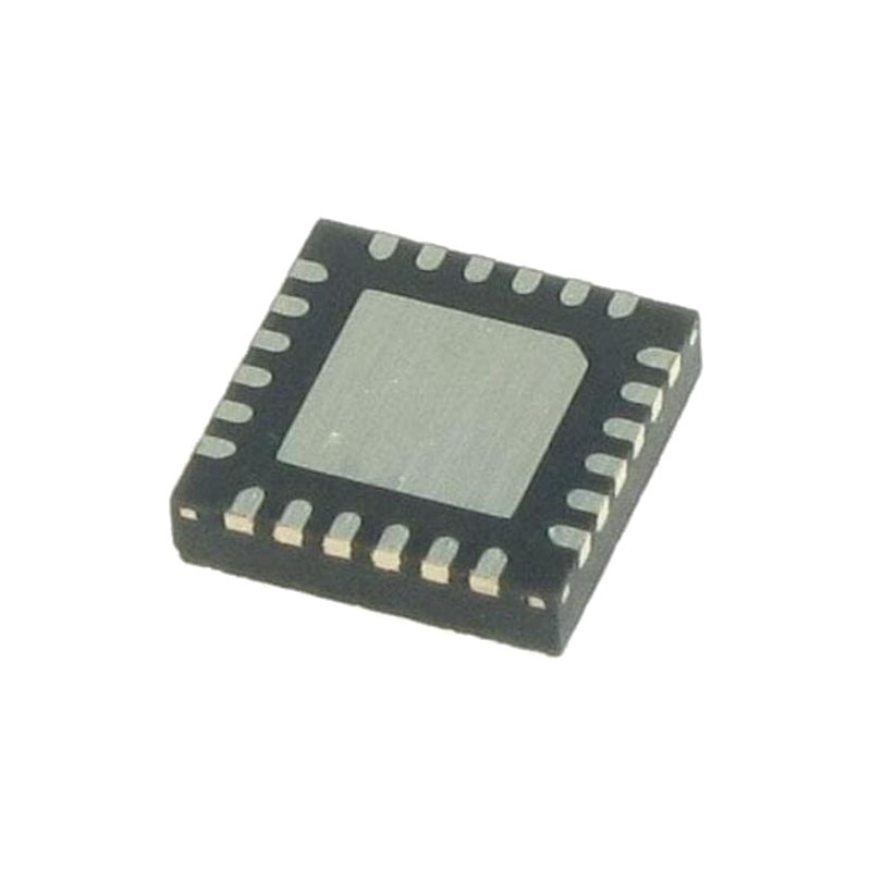
Encapsulado QFN de 16 terminales de 3 mm × 3 mm y bajo perfil
APLICACIONES
Teléfonos inteligentes
Módems inalámbricos y DSL
Cámaras digitales
Instrumentos portátiles
Regulación del punto de carga
OPERACIÓN
LAZO DE CONTROL PRINCIPAL
El LTC3545/LTC3545-1 utiliza una arquitectura reductora de frecuencia constante y modo de corriente. Tanto el interruptor principal (MOSFET de canal P) como el síncrono (MOSFET de canal N) son internos. Durante el funcionamiento normal, el MOSFET de potencia superior interno se enciende en cada ciclo cuando el oscilador activa el enclavamiento RS, y se apaga cuando el comparador de corriente, ICOMP , restablece el enclavamiento RS. El pico de corriente del inductor al que ICOMP reinicia el RS latch, está controlado por la salida del amplificador de error EA. Cuando la corriente de carga aumenta, provoca una ligera disminución de la tensión de realimentación FB con respecto a la referencia de 0,6 V, lo que a su vez hace que la tensión de salida del amplificador EA aumente hasta que la corriente media del inductor coincida con la nueva corriente de carga. Mientras el MOSFET superior está apagado, el MOSFET inferior se enciende hasta que la corriente del inductor empieza a invertirse, como indica el comparador de inversión de corriente, IRCMP , o hasta el principio del siguiente ciclo de reloj.
SALTO DE IMPULSO/MODO RÁFAGA FUNCIONAMIENTO
Con cargas ligeras, la corriente del inductor puede llegar a cero o invertirse en cada impulso. El MOSFET inferior es apagado por el comparador de inversión de corriente, IRCMP , y la tensión de conmutación sonará. Esto es funcionamiento en modo discontinuo, y es un comportamiento normal para el regulador de conmutación.
Con cargas muy ligeras, el LTC3545/LTC3545-1 empezará a funcionar automáticamente en modo de omisión de impulsos o en modo ráfaga, dependiendo del estado de la patilla MODE/SYNC (LTC3545). En cualquier caso, la pieza empezará a omitir ciclos para mantener la regulación.
OPERACIÓN
SOFT-START
El arranque suave reduce las sobrecorrientes en VIN y el sobreimpulso de salida durante el arranque. El arranque suave en el LTC3545/LTC3545-1 se implementa mediante la rampa interna de la señal de referencia alimentada al amplificador de error durante aproximadamente un período de 1 ms.
OPERACIÓN DE ABANDONO
A medida que la tensión de alimentación de entrada disminuye hasta un valor cercano a la tensión de salida, el ciclo de trabajo aumenta hacia el tiempo de conexión máximo. Una mayor reducción de la tensión de alimentación obliga al interruptor principal a permanecer encendido durante más de un ciclo hasta alcanzar el ciclo de trabajo 100%. La tensión de salida vendrá entonces determinada por la tensión de entrada menos la caída de tensión a través del MOSFET de canal P y el inductor. Un detalle importante que hay que recordar es que a tensiones de alimentación de entrada bajas, la RDS(ON) del interruptor del canal P aumenta. Por lo tanto, el usuario debe calcular la disipación de potencia cuando el LTC3545/LTC3545-1 se utiliza a un ciclo de trabajo de 100% con una tensión de entrada baja.
Selección del núcleo inductor
Los distintos materiales y formas del núcleo modifican la relación tamaño/corriente y precio/corriente de un inductor. Los núcleos toroidales o blindados de ferrita o materiales de aleación permanente son pequeños y no irradian mucha energía, pero generalmente cuestan más que los inductores de núcleo de hierro pulverizado con características eléctricas similares. La elección del tipo de inductor que se va a utilizar depende más de los requisitos de precio frente a tamaño y de los requisitos de campo radiado/EMI que de lo que el LTC3545/LTC3545-1 necesita para funcionar.