Descripción
El NB7L1008M es un búfer de salida en abanico diferencial 1:8 de reloj/datos de alto rendimiento. El NB7L1008M produce ocho copias de salida idénticas de Reloj o Datos que funcionan hasta 6 GHz o 10,7 Gb/s, respectivamente. Como tal, el NB7L1008M es ideal para SONET, GigE, canal de fibra, backplane y otras aplicaciones de distribución de reloj/datos. Las entradas diferenciales incorporan resistencias de terminación internas de 50 a las que se accede a través de la patilla VT. Esta característica permite al NB7L1008M aceptar varios estándares lógicos, como LVPECL, CML, LVDS, LVCMOS o niveles lógicos LVTTL. La salida de referencia VREFAC se puede utilizar para volver a polarizar señales de entrada diferenciales o de un solo extremo acopladas con condensador. El diseño fanout 1:8 se ha optimizado para aplicaciones de baja desviación de salida. El NB7L1008M es un miembro de la familia GigaComm de productos de reloj de alto rendimiento.
Características
Velocidad de datos de entrada > 12 Gb/s típica
Fluctuación en función de los datos < 20 ps
Frecuencia de reloj de entrada máxima > 8 GHz típica
Fluctuación aleatoria del reloj < 0,8 ps RMS
Salidas CML 1:8 de baja desviación, < 25 ps máx.
Entradas multinivel, acepta LVPECL, CML, LVDS
160 ps Retardo de propagación típico
45 ps Tiempos típicos de subida y bajada
Salidas diferenciales CML, 400 mV pico a pico, típico
Rango de funcionamiento: VCC = 2,375 V a 3,6 V, GND = 0 V
Resistencias internas de terminación de entrada, 50
VREFAC Salida de referencia
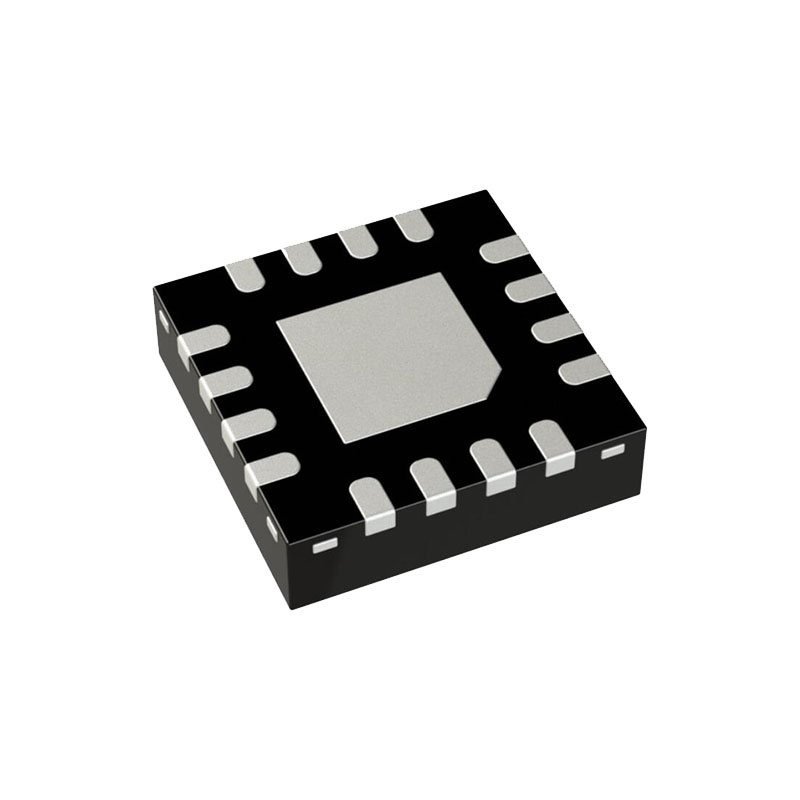
Encapsulado QFN-32, 5 mm x 5 mm
-40°C a +85°C Temperatura ambiente de funcionamiento
Dispositivos sin Pb
Más información
DESCRIPCIÓN DEL PIN
En la configuración diferencial, cuando la patilla de terminación de entrada (VT) se conecta a una tensión de terminación común o se deja abierta, y si no se aplica ninguna señal en IN/IN , el dispositivo será susceptible de autooscilación. Las salidas Qn/Qn tienen resistencias internas de terminación de fuente de 50Ω.
Todos los pines VCC y GND deben estar conectados externamente a la misma tensión de alimentación para garantizar el correcto funcionamiento del dispositivo.
VALORES MÁXIMOS
Las tensiones superiores a las indicadas en la tabla de valores máximos pueden dañar el dispositivo. Si se supera alguno de estos límites, no debe asumirse la funcionalidad del dispositivo, pueden producirse daños y la fiabilidad puede verse afectada.
Placa multicapa estándar JEDEC - 2S2P (2 de señal, 2 de alimentación) con 8 vías térmicas rellenas bajo el pad expuesto.
El dispositivo cumplirá las especificaciones una vez establecido el equilibrio térmico cuando se monte en un zócalo de prueba o en una placa de circuito impreso con un flujo de aire transversal mantenido superior a 500 lfpm.
Salidas CML cargadas con 50 a VCC para un funcionamiento correcto.
Los parámetros de entrada y salida varían 1:1 con VCC.
Los parámetros Vth, VIH, VIL y VISE deben cumplirse simultáneamente.
Vth se aplica a la entrada complementaria cuando se opera en modo single-ended.
Los parámetros VIHD, VILD, VID y VCMR deben cumplirse simultáneamente
CARACTERÍSTICAS AC
El dispositivo cumplirá las especificaciones una vez establecido el equilibrio térmico cuando se monte en un zócalo de prueba o en una placa de circuito impreso con un flujo de aire transversal mantenido superior a 500 lfpm.
Medido utilizando una fuente de 400 mV, ciclo de trabajo 50% fuente de reloj de 1 GHz. Todas las salidas deben cargarse con 50Ω externos a VCC. Velocidades de flanco de entrada 40 ps (20% - 80%).
La oscilación de la tensión de salida es una medición de un solo extremo que funciona en modo diferencial.
VIHDMIN≥1100 mV.
El sesgo del ciclo de trabajo se mide entre las salidas diferenciales utilizando las desviaciones de la suma de Tpw- y Tpw+ a 1 GHz.
El sesgo dentro del dispositivo compara los bordes coincidentes.
La desviación de dispositivo a dispositivo se mide entre salidas bajo una transición idéntica
Fluctuación aditiva del RELOJ con la señal de reloj de ciclo de trabajo 50%.
Fluctuación aditiva de pico a pico con datos NRZ de entrada en PRBS23.
La oscilación de la tensión de entrada es una medición de un solo extremo que funciona en modo diferencial.
Placa multicapa estándar JEDEC - 2S2P (2 de señal, 2 de alimentación) con 8 vías térmicas rellenas bajo el pad expuesto.


