Descripción
Este búfer de doble Schmitt-Trigger está diseñado para V de 1,65 V a 5,5 VCC operación.
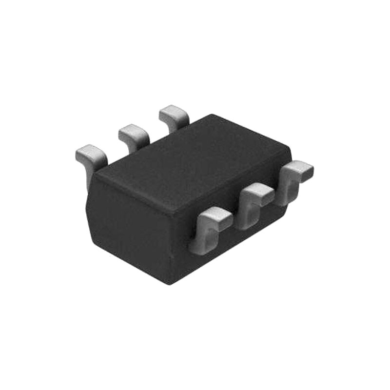
El dispositivo SN74LVC2G17 contiene dos búferes y realiza la función booleana Y = A. El dispositivo funciona como dos búferes independientes, pero debido a la acción Schmitt, puede tener diferentes niveles de umbral de entrada para la entrada positiva (VT+) y negativo (VT-). La tecnología de encapsulado NanoFree™ supone un gran avance en los conceptos de encapsulado de CI, ya que utiliza la matriz como encapsulado.
Este dispositivo está totalmente especificado para aplicaciones de apagado parcial utilizando Ifuera de. El Ifuera de desactiva las salidas, evitando el retorno de corriente dañina a través del dispositivo cuando se apaga.
Características
- Las entradas Schmitt-Trigger proporcionan histéresis
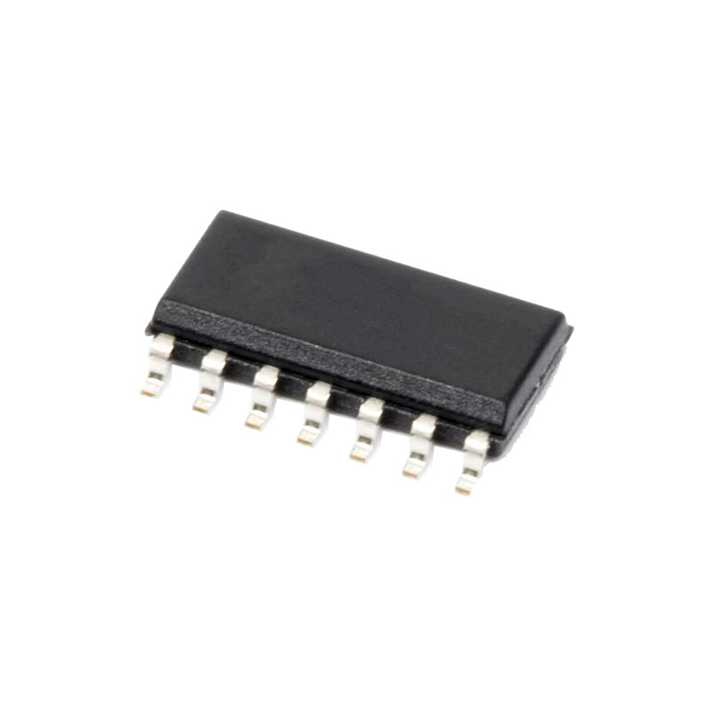
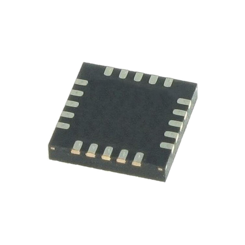
- Disponible en el paquete NanoFree™ de Texas Instruments
- Admite 5 V VCC Operación
- Las entradas aceptan tensiones de hasta 5,5 V
- Maxtpd de 5,4 ns a 3,3 V
- Bajo consumo, 10-μA máx. ICC
- ±24 mA Potencia de salida a 3,3 V
- V típicoOLP (rebote de tierra de salida) < 0,8 V a VCC = 3,3 V, TA = 25°C
- V típicoOHV (Salida VOH subimpulso) > 2 Vat VCC = 3,3 V, TA = 25°C
- Ifuera de Admite inserción en vivo, funcionamiento en modo de apagado parcial y protección contra retroceso
- Rendimiento de enclavamiento superior a 100 mA según JESD 78, Clase II
- La protección ESDP supera la norma JESD 22
- Modelo de cuerpo humano 2000-V
- Modelo de dispositivo cargado de 1000 V
Aplicaciones
- Receptores AV
- Bases de audio: Portátil
- Reproductores Blu-ray y cine en casa
- Reproductores/grabadores MP3
- Asistentes digitales personales (PDA)
- Alimentación: Telecom/Servidor Alimentación AC/DC: Controlador único: Analógico y digital
- Unidades de estado sólido (SSD): Clientes y empresas
- Televisores: LCD/Digital y de alta definición (HDTV)
- Tabletas: Empresa
- Análisis de vídeo: Servidor
- Auriculares, teclados y ratones inalámbricos
Valores máximos absolutos
(1) Las tensiones superiores a las indicadas en Valores máximos absolutos pueden provocar daños permanentes en el dispositivo. Se trata únicamente de valores nominales de tensión, y no se da a entender el funcionamiento del dispositivo en estas condiciones o en cualquier otra más allá de las indicadas en Condiciones de funcionamiento recomendadas. La exposición a las condiciones máximas absolutas durante periodos prolongados puede afectar a la fiabilidad del dispositivo.
(2)Los valores nominales de tensión negativa de entrada y tensión de salida pueden superarse si se respetan los valores nominales de corriente de entrada y salida.
(3)El valor de VCC en la tabla Condiciones de funcionamiento recomendadas.
Clasificaciones ESD
(1) Descarga electrostática (ESD) para medir la sensibilidad del dispositivo y la inmunidad a los daños causados por las descargas electrostáticas de la línea de montaje en el dispositivo.
(2) El documento JEP155 del JEDEC afirma que el HBM de 500 V permite una fabricación segura con un proceso de control ESD estándar.
(3) El documento JEP157 del JEDEC afirma que el CDM de 250 V permite una fabricación segura con un proceso de control ESD estándar.
Visión general
La tecnología de envasado NanoFree™ supone un gran avance en los conceptos de envasado de circuitos integrados, ya que utiliza la matriz como envase.
Este dispositivo está totalmente especificado para aplicaciones de apagado parcial utilizando Ifuera de. El Ifuera de desactiva las salidas, evitando el retorno de corriente dañina a través del dispositivo cuando se apaga.
Descripción
- Rango de tensión de funcionamiento de 1,65 V a 5,5 V
- Permite bajar la tensión
- 5Va3,3 V
- 5 V o 3,3 V a 1,8 V
- Las entradas aceptan tensiones de hasta 5,5 V
- 5-Vtolerancia en el pin de entrada
- Función Ioff
- Permite tensión en las entradas y salidas cuando VCC es 0 V
- Capaz de reducir las fugas cuando VCC es 0 V
- La entrada Schmitt-Trigger puede mejorar la capacidad de inmunidad al ruido
Introducción detallada de parámetros
Información sobre la solicitud
El dispositivo SN74LVC2G17 contiene dos búferes y realiza la función booleana Y = A. El dispositivo funciona como dos búferes independientes, pero debido a la acción Schmitt, puede tener diferentes niveles de umbral de entrada para la entrada positiva (VT+) y negativo (VT-).
Requisitos de diseño
Este dispositivo utiliza tecnología CMOS y tiene salida equilibrada. Debe tenerse cuidado para evitar la contención del bus porque puede conducir corrientes que excederían los límites máximos. Las salidas pueden combinarse para producir un accionamiento más alto, pero el accionamiento alto también creará bordes más rápidos en cargas ligeras, por lo que deben tenerse en cuenta las condiciones de enrutamiento y carga para evitar el timbre.
Directrices de diseño
Cuando se utilizan dispositivos lógicos de bits múltiples, las entradas no deben flotar. En muchos casos, las funciones o partes de funciones de los dispositivos lógicos digitales no se utilizan. Algunos ejemplos son cuando sólo se utilizan dos entradas de una puerta AND de triple entrada, o cuando sólo se utilizan 3 de las puertas de 4 búferes. Estos pines de entrada no deben dejarse sin conectar porque las tensiones indefinidas en las conexiones exteriores dan lugar a estados operativos indefinidos.