DESCRIPTION GÉNÉRALE
The AD9102 TxDAC and waveform generator is a high performance digital-to-analog converter (DAC) integrating on-chip pattern memory for complex waveform generation with a direct digital synthesizer (DDS). The DDS is a 14-bit output, up to 180 MSPS main clock sine wave generator with a 24-bit tuning word, allowing 10.8 Hz/LSB frequency resolution.SRAM data can include directly generated stored waveforms, amplitude modulation patterns applied to DDS outputs, or DDS frequency tuning words. An internal pattern control state machine lets the user program the pattern period for the DAC as well the start delay within the pattern period for the signal output on the DAC. A SPI interface is used to configure the digital waveform generator and load patterns into the SRAM. A gain adjustment factor and an offset adjustment are applied to the digital signal on their way into the DAC. The AD9102 offers exceptional ac and dc performance and supports DAC sampling rates of up to 180 MSPS. The flexible power supply operating range of 1.8 V to 3.3 V and low power dissipation of the AD9102 make it well suited for portable and low power applications.
POINTS FORTS DU PRODUIT
High Integration: On-chip DDS and 4096 × 14 pattern memory
Low Power: Power-down mode provides for low power idle periods
Flexible Operation: 3- or 4-wire SPI interface; 1.8 V or 3.3 V supply
CARACTÉRISTIQUES
On-chip 4096 × 14-bit pattern memory
On-chip DDS
Power dissipation @ 3.3 V, 4 mA output
96.54 mW @ 180 MSPS
Sleep mode: <5 mW @ 3.3 V
Supply voltage: 1.8 V to 3.3 V
SFDR to Nyquist
87 dBc @ 10 MHz output
Phase noise @ 1 kHz offset, 180 MSPS, 8 mA: −150 dBc/Hz
Differential current outputs: 8 mA max @ 3.3 V
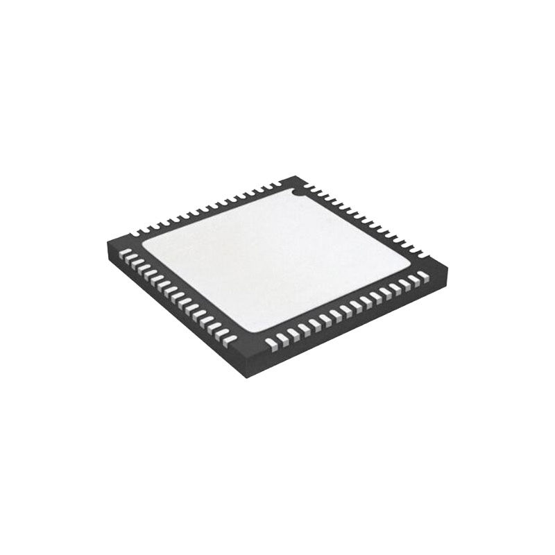
Small footprint, 32-lead, 5 mm × 5 mm LFCSP with 3.6 mm × 3.6 mm exposed paddle, and Pb-free package
CANDIDATURES
Instruments médicaux
Portable instrumentation
Signal generators, arbitrary waveform generators
Automotive radar
INFORMATIONS SUR LES APPLICATIONS
WAVEFORM GENERATION SETUPS AND SAMPLE SEQUENCE
A sample sequence for generating DDS waveforms is as follows:
- Set initial values of I/O pins ( RESET, TRIGGER, and Logic 1 (high).
- Set SPI frequency and mode as preferred.
- Assert RESET (Pin 9) by pulsing from Logic 0 (low) then Logic 1 (high) to reset register values. Deassert RESET afterward.
- Proceed with register read and write for DDS as follows:
- Set DDS output frequency in DDSTW_MSB (Register 0x3E, Bits[15:0]) and DDSTW_LSB (Register 0x3F, Bits[15:8]).
- (Optional) Set number of DDS cycles in DDS_CYC. For this, WAVE_SEL in WAV_CONFIG must be set to 0x2.
- (Optional) Set phase offset for DDS output in DDS_PW (Register 0x43).
- Write to or read from SPI registers. Update the RUN bit and the RAMUPDATE bit and the end of the write sequence as follows:
- Set waveform select to DDS in WAV_CONFIG (Register 0x27).
- Set DAC digital gain in DAC_DGAIN (Register 0x35).
- (Optional) Set DAC digital offset in DACDOF (Register 0x25).
- Update the RUN bit (Register 0x1E).
- Update the RAMUPDATE bit (Register 0x1D).
- Set Trigger terminal (Pin 32) to Logic 0 (low) to start pattern generation.
A sample sequence for generating SRAM waveforms is as follows:
- Set initial values of I/O pins ( RESET, TRIGGER, and Logic 1 (high).
- Set SPI frequency and mode as preferred.
- Assert RESET (Pin 9) by pulsing from Logic 0 (low) then Logic 1 (high) to reset register values. Deassert RESET afterward.
- Write data to SRAM. Set PAT_STATUS (Register 0x1E) = 0x04 as follows:
- BUF_READ (Bit 3) = 0
- MEM_ACCESS (Bit 2) = 1
- RUN (Bit 0) = 0
- Write left-justified data to SRAM registers (0x6000 to 0x6FFF address space). After writing, disable the MEM_ACCESS bit.
- Read data from SRAM. Set PAT_STATUS (Register 0x1E) = 0x0C as follows:
- BUF_READ (Bit 3) = 1
- MEM_ACCESS (Bit 2) = 1
- RUN (Bit 0) = 0
- After reading data from SRAM registers, disable the BUF_READ and MEM_ACCESS bits.