DESCRIPTION
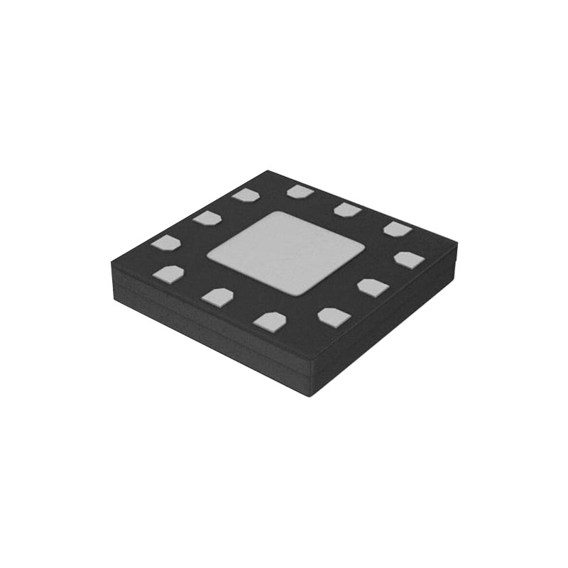
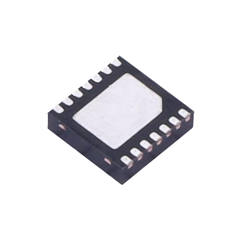
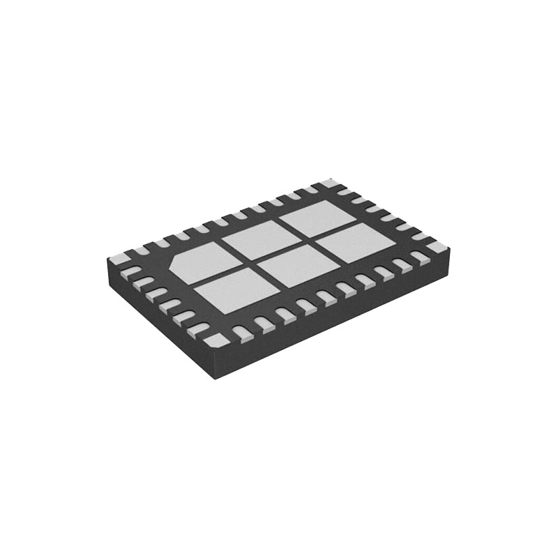
The LT1963A series are low dropout regulators optimized for fast transient response. The devices are capable of supplying 1.5A of output current with a dropout voltage of 340mV. Operating quiescent current is 1mA, dropping to <1µA in shutdown. Quiescent current is well controlled; it does not rise in dropout as it does with many other regulators. In addition to fast transient response, the LT1963A regulators have very low output noise which makes them ideal for sensitive RF supply applications. Output voltage range is from 1.21V to 20V. The LT1963A regulators are stable with output capacitors as low as 10µF. Internal protection circuitry includes reverse battery protection, current limiting, thermal limiting and reverse current protection. The devices are available in fixed output voltages of 1.5V, 1.8V, 2.5V, 3.3V and as an adjustable device with a 1.21V reference voltage. The LT1963A regulators are available in 5-lead TO-220, DD, 3-lead SOT-223, 8-lead SO and 16-lead TSSOP packages.
CARACTÉRISTIQUES
Optimized for Fast Transient Response
Output Current: 1.5A
Dropout Voltage: 340mV
Low Noise: 40µVRMS (10Hz to 100kHz)
1mA Quiescent Current
Aucune diode de protection n'est nécessaire
Controlled Quiescent Current in Dropout
Fixed Output Voltages: 1.5V, 1.8V, 2.5V, 3.3V
Adjustable Output from 1.21V to 20V
<1µA Quiescent Current in Shutdown
Stable with 10µF Output Capacitor*
Stable with Ceramic Capacitors*
Reverse Battery Protection
Pas de courant inverse
Limitation thermique
5-Lead TO-220, DD, 3-Lead SOT-223 and 8-Lead SO Packages
Qualification AEC-Q100 pour les applications automobiles
CANDIDATURES
3.3V to 2.5V Logic Power Supplies
Post-régulateur pour alimentations à découpage
INFORMATIONS SUR LES APPLICATIONS
The LT1963A series are 1.5A low dropout regulators optimized for fast transient response. The devices are capable of supplying 1.5A at a dropout voltage of 350mV. The low operating quiescent current (1mA) drops to less than 1µA in shutdown. In addition to the low quiescent current, the LT1963A regulators incorporate several protection features which make them ideal for use in battery-powered systems. The devices are protected against both reverse input and reverse output voltages. In battery backup applications where the output can be held up by a backup battery when the input is pulled to ground, the LT1963A-X acts like it has a diode in series with its output and prevents reverse current flow. Additionally, in dual supply applications where the regulator load is returned to a negative supply, the output can be pulled below ground by as much as 20V and still allow the device to start and operate.
Fonctionnement réglable
The adjustable version of the LT1963A has an output voltage range of 1.21V to 20V. The device servos the output to maintain the voltage at the ADJ pin at 1.21V referenced to ground. The current in R1 is then equal to 1.21V/R1 and the current in R2 is the current in R1 plus the ADJ pin bias current. The ADJ pin bias current, 3µA at 25°C, flows through R2 into the ADJ pin. The output voltage can be calculated using the formula in Figure 2. The value of R1 should be less than 4.17k to minimize errors in the output voltage caused by the ADJ pin bias current. Note that in shutdown the output is turned off and the divider current will be zero. The adjustable device is tested and specified with the ADJ pin tied to the OUT pin for an output voltage of 1.21V. Specifications for output voltages greater than 1.21V will be proportional to the ratio of the desired output voltage to 1.21V: VOUT/1.21V. For example, load regulation for an output current change of 1mA to 1.5A is –3mV typical at VOUT = 1.21V. At VOUT = 5V, load regulation is: (5V/1.21V)(–3mV) = –12.4mV
Output Capacitors and Stability
The LT1963A regulator is a feedback circuit. Like any feedback circuit, frequency compensation is needed tomake it stable. For the LT1963A, the frequency compensation is both internal and external—the output capacitor. The size of the output capacitor, the type of the output capacitor, and the ESR of the particular output capacitor all affect the stability. In addition to stability, the output capacitor also affects the high frequency transient response. The regulator loop has a finite band width. For high frequency transient loads, recovery from a transient is a combination of the output capacitor and the bandwidth of the regulator. The LT1963A was designed to be easy to use and accept a wide variety of output capacitors. However, the frequency compensation is affected by the output capacitor and optimum frequency stability may require some ESR, especially with ceramic capacitors.