DESCRIPTION
The LTC2962 series of configurable power supply monitors can supervise systems with up to four supply voltages. One of 16 preset or adjustable voltage monitor thresholds per channel can be selected using external 1% resistors connected to the programming (PG) inputs. The preset voltage thresholds are accurate to ±0.5% over temperature. Positive (+ADJ) and negative (–ADJ) adjustable inputs with a 0.5V threshold allow undervoltage, negative voltage and overvoltage monitoring.
The watchdog (LTC2963 only) and reset timeout periods are adjustable using external capacitors. Accurate voltage thresholds and comparator glitch immunity ensure reliable reset operation without false triggering. The RST output is guaranteed to be in the correct state for VCC input voltage down to 1V.
The flexibility of the LTC2962 family provides the ability to monitor a wide variety of power supply combinations, including multiple supplies of the same voltage, with ±0.5% accuracy.
CARACTÉRISTIQUES
Simultaneously Monitor Four Power Supplies
±0.5% Threshold Accuracy Over Temperature
Selectable –4% and –6% Thresholds per Supply: 5V, 3.3V, 2.5V, 1.8V, 1.5V, 1.2V, 1V and ±ADJ
Adjustable Reset (RST) Timeout
Overvoltage and Negative Voltage Monitoring
Push-Pull or Open-Drain RST Output
Margin Pin RDIS for Reset Disable
H-Grade Temperature Range
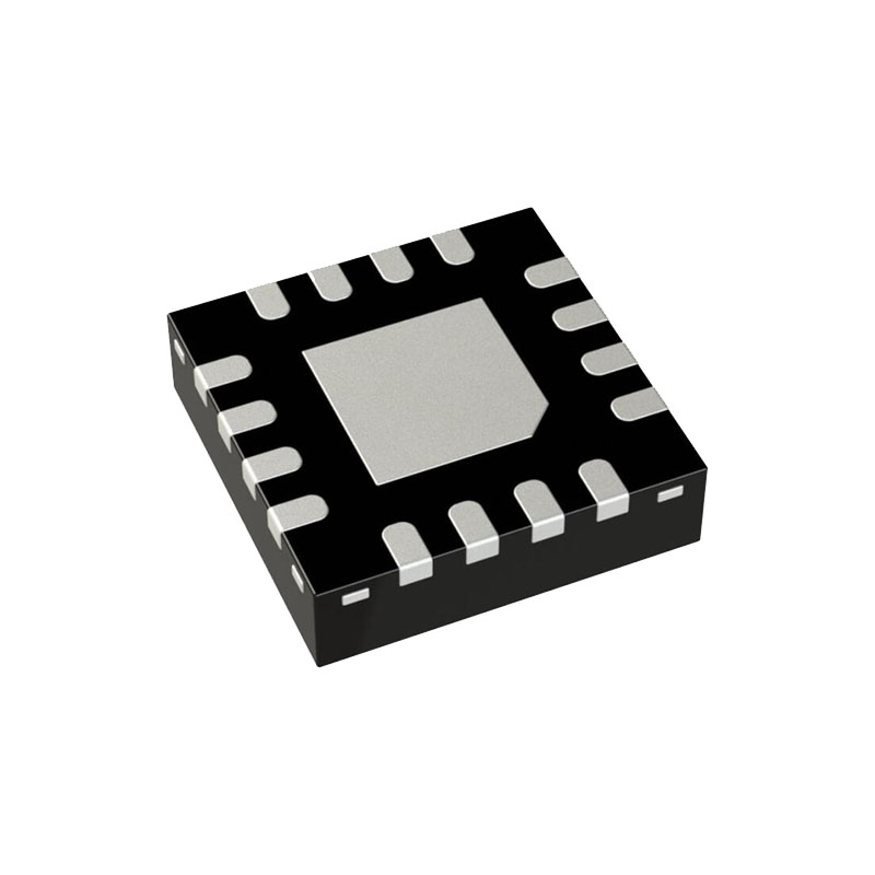
16-Lead 3mm × 3mm QFN (LTC2962)
CANDIDATURES
High Reliability Systems
Network, Telecom and Server Systems
Automotive Control Systems
FONCTIONNEMENT
The LTC2962 family monitors up to four power supplies (or channels) with industry leading ±0.5% accuracy over a wide temperature range. While primarily intended for monitoring undervoltage (UV) events, the LTC2962 family has a mode allowing for overvoltage (OV) monitoring. In typical operation, if any of the monitored supplies fall below a predetermined threshold, the reset output, RST, pulls low immediately. When all four supplies rise above their threshold (or below, in the case of –ADJ mode), the reset output is released after a timeout period. The reset timeout can be a fixed 200ms or it can be adjusted using an external capacitor. The reset output is held low during power-up, power-down and brownout conditions on any channel.
±ADJ modes and fourteen UV thresholds can be configured for each channel individually. Each of the four program (PG) inputs select one of sixteen voltage monitor thresholds for each input respectively. During power-up, a 4-bit ADC converts the voltage on each PG input. The resultant digital value is decoded into one of the sixteen threshold options. This technique allows for 1% standard resistors to be used to configure the PG inputs while maintaining tight ±0.5% accuracy for each threshold. 65,536 different threshold combinations can be selected with the LTC2962 family, including the ability to monitor the same voltage on more than one channel. The +ADJ and –ADJ modes compare the channel inputs to 0.5V. With an external resistive divider, +ADJ can be used to monitor any voltage greater than 0.5V. –ADJ can be used as an overvoltage monitor for positive supplies or an undervoltage monitor for negative supplies.
INFORMATIONS SUR LES APPLICATIONS
Threshold Accuracy
The LTC2962 family features outstanding accuracy.Consider a system device whose operation requires 1V ± 4.5% tolerance. In other words, to guarantee proper operation, the manufacturer states that the voltage presented to the device remain between 0.955V and 1.045V.In an ideal world, the power supply providing voltage to this device could vary over that entire range, and an ideal undervoltage supervisor for the supply would generate a reset at exactly 0.955V. However, no supervisor is perfect. The actual reset threshold of a supervisor varies over a specified range; the LTC2962 family varies ±0.5% around its nominal threshold voltage over temperature.
PCB Layout
The LTC2962 family is a precision device whose comparator thresholds are factory trimmed to ±0.5% accuracy as shown in the Typical Performance Characteristics section. The mechanical stress caused by soldering parts to a printed circuit board may cause the threshold to shift and the temperature coefficient to change. While every situation is different, expected errors due to these effects are likely to be on the order of 0.05%. To reduce the effects of stress-related shifts, mount the device near the short edge of a printed circuit board or in a corner. In addition, slots can be cut into the board on two sides of the device to reduce mechanical stress. A thicker and smaller board is stiffer and less prone to bend. Finally, use stress relief, such as flexible standoffs, when mounting the board.

