説明
The AT24C01C/AT24C02C provides 1,024/2,048 bits of Serial Electrically Erasable and Programmable Read-Only Memory (EEPROM) organized as 128/256 words of 8 bits each. The device’s cascading feature allows up to eight devices to share a common two‑wire bus. This device is optimized for use in many industrial and commercial applications where low-power and low-voltage operations are essential.
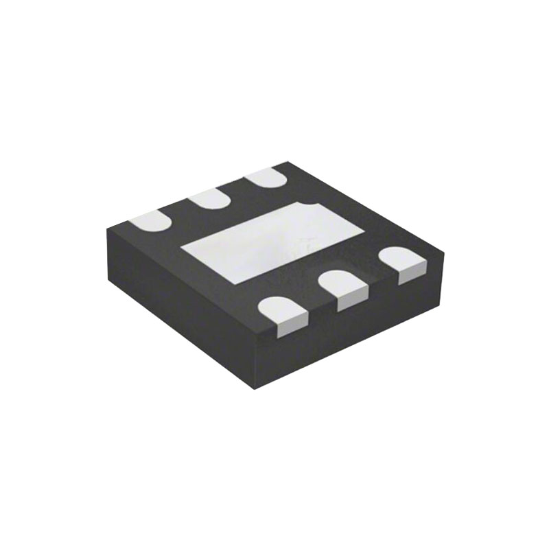
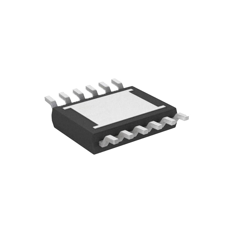
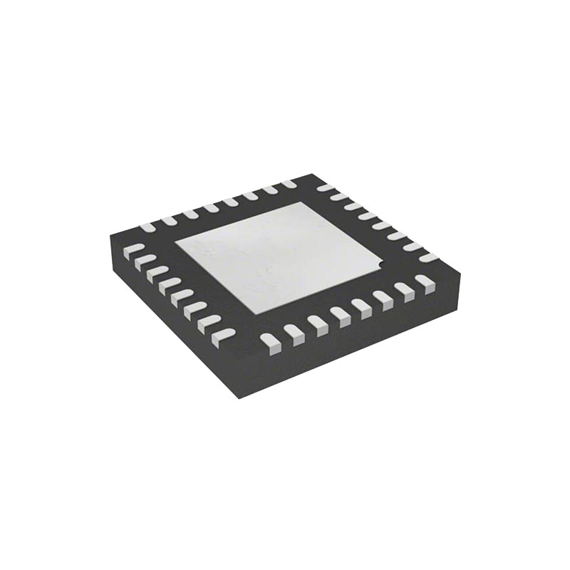
The device is available in space-saving 8-lead SOIC, 8-lead TSSOP, 8-pad UDFN, 8-lead PDIP, 5-lead SOT23 and 8-ball VFBGA packages. All packages operate from 1.7V to 5.5V.
特徴
• Low-Voltage Operation:
- VCC = 1.7V~5.5V
• Internally Organized as 128 x 8 (1K) or 256 x 8 (2K)
- 工業用温度範囲:-40°C~+85°C
- I2C互換(2線式)シリアルインターフェース:
- 100 kHz 標準モード、1.7V~5.5V
- 400 kHz 高速モード、1.7V~5.5V
- 1 MHz高速モードプラス(FM+)、2.5V~5.5V
- シュミット・トリガー、ノイズ抑制のためのフィルター付き入力
- 双方向データ転送プロトコル
- フルアレイ・ハードウェアデータ保護用ライトプロテクト端子
- 超低アクティブ電流(最大3 mA)およびスタンバイ電流(最大6 μA)
• 8-Byte Page Write Mode:
- 部分的なページの書き込みが可能
- ランダム・リード・モードとシーケンシャル・リード・モード
- 最大5ms以内の自己タイミング書き込みサイクル
• ESD Protection > 4,000V
- 高い信頼性:
- 耐久性:1,000,000書き込みサイクル
- データの保持100年
- グリーンパッケージオプション(鉛フリー/ハライドフリー/RoHS対応)
- ダイセール・オプションウェハフォームとバンプ付きウェハ
デバイス・アドレス入力(A0、A1、A2)
A0、A1、A2ピンは、他の2線式シリアルEEPROMデバイスとの互換性のために、ハード配線(直接GNDまたはVCCへ)されたデバイスアドレス入力です。ピンがハード配線されている場合、1つのバス・システムで最大8つのデバイスをアドレス指定することができます。デバイスは、対応するハードウェアとソフトウェアが一致したときに選択される。これらのピンがフローティングのままであれば、A0、A1、A2ピンは内部でGNDにプルダウンされる。しかし、カスタマ・アプリケーションでは容量性カップリングが発生する可能性があるため、Microchip 社はアドレス・ピンを常に既知の状態に接続することを推奨します。プルアップ抵抗を使用する場合、Microchip 社は 10 kΩ 以下を推奨します。
Serial Data (SDA)
The SDA pin is an open-drain bidirectional input/output pin used to serially transfer data to and from the device. The SDA pin must be pulled high using an external pull-up resistor (not to exceed 10 kΩ in value) and may be wire-ORed with any number of other open-drain or open-collector pins from other devices on the same bus.
Serial Clock (SCL)
The SCL pin is used to provide a clock to the device and to control the flow of data to and from the device. Command and input data present on the SDA pin is always latched in on the rising edge of SCL, while output data on the SDA pin is clocked out on the falling edge of SCL. The SCL pin must either be forced high when the serial bus is idle or pulled high using an external pull-up resistor.
Write-Protect (WP)
The write-protect input, when connected to GND, allows normal write operations. When the WP pin is connected directly to VCC, all write operations to the protected memory are inhibited.
If the pin is left floating, the WP pin will be internally pulled down to GND. However, due to capacitive coupling that may appear in customer applications, Microchip recommends always connecting the WP pin to a known state. When using a pull‑up resistor, Microchip recommends using 10 kΩ or less.
Device Reset
To prevent inadvertent write operations or any other spurious events from occurring during a power-up sequence, the AT24C01C/AT24C02C includes a Power-on Reset (POR) circuit. Upon power-up, the device will not respond to any commands until the VCC level crosses the internal voltage threshold (VPOR) that brings the device out of Reset and into Standby mode.