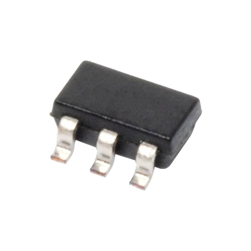
概要
REF19xシリーズ高精度バンドギャップ電圧リファレンスは、特許取得済みの温度ドリフト曲率補正回路と、高安定薄膜抵抗器のレーザートリミングにより、非常に低い温度係数と高い初期精度を実現しています。
REF19xシリーズはマイクロパワー、低ドロップアウト電圧(LDV)デバイスで構成され、出力電圧より100mV低い電源から安定した出力電圧を供給し、消費電流は45μA未満です。SLEEPピンにTTLまたはCMOSの低レベルを印加することで有効になるスリープ・モードでは、出力はオフになり、電源電流はさらに15μA未満に低減されます。
REF19xシリーズ・リファレンスは、産業用拡張温度範囲(-40°C~+85°C)で仕様化されており、車載用などのアプリケーションでは-40°C~+125°Cで標準的な性能を発揮します。
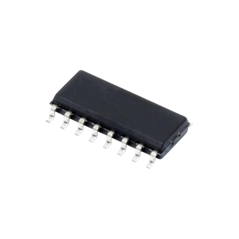
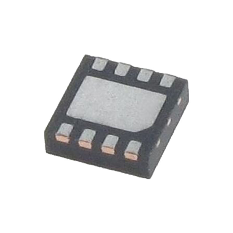
すべての電気グレードは8リードSOICパッケージで提供され、PDIPおよびTSSOPパッケージは最低電気グレードでのみ提供される。
特徴
温度係数:最大5 ppm/°C
高出力電流:30 mA
低電源電流:最大45μA
初期精度:最大±2 mV1
スリープモード:最大15μA
低入出力電圧
負荷調整:4ppm/mA
ライン・レギュレーション4ppm/V
短絡保護
アプリケーション
ポータブル機器
ADCとDAC
スマートセンサー
ソーラー・アプリケーション
ループ電流駆動計器
アプリケーション情報
OUTPUT SHORT-CIRCUIT BEHAVIOR
The REF19x family of devices is totally protected from damage due to accidental output shorts to GND or to VS. In the event of an accidental short-circuit condition, the reference device shuts down and limits its supply current to 40 mA.
デバイスの消費電力に関する考察
REF19xファミリーのリファレンスは、3.3V~15Vの入力電圧で30mAの負荷電流を流すことができます。最大許容損失またはジャンクション温度の公表仕様を超えると、デバイスが早期に故障する可能性があります。
出力電圧バイパス
For stable operation, low dropout voltage regulators and references generally require a bypass capacitor connected from their VOUT pins to their GND pins. Although the REF19x family of references is capable of stable operation with capacitive loads exceeding 100 μF, a 1 μF capacitor is sufficient to guarantee rated performance. The addition of a 0.1 μF ceramic capacitor in parallel with the bypass capacitor improves load current transient performance. For best line voltage transient performance, it is recommended that the voltage inputs of these devices be bypassed with a 10 μF electrolytic capacitor in parallel with a 0.1 μF ceramic capacitor.
SLEEP MODE OPERATION
All REF19x devices include a sleep capability that is TTL/CMOSlevel compatible. Internally, a pull-up current source to VS is connected at the SLEEP pin. This permits the SLEEP pin to be driven from an open collector/drain driver. A logic low or a 0 V condition on the SLEEP pin is required to turn off the output stage. During sleep, the output of the references becomes a high impedance state where its potential would then be determined by external circuitry. If the sleep feature is not used, it is recommended that the SLEEP pin be connected to VS .
アプリケーションでは、基準電圧をデジタル制御し、1つの安定した電圧と2つ目の安定した電圧の間で選択することがよく要求される。REF19xシリーズ固有のスリープ機能により、スイッチ出力リファレンス構成はハードウェアをほとんど追加することなく簡単に実装できます。
テストピン
Test Pin 1 and Test Pin 5 are reserved for in-package Zener zap. To achieve the highest level of accuracy at the output, the Zener zapping technique is used to trim the output voltage. Because each unit may require a different amount of adjustment, the resistance value at the test pins varies widely from pin to pin and from part to part. The user should leave Pin 1 and Pin 5 unconnected.


