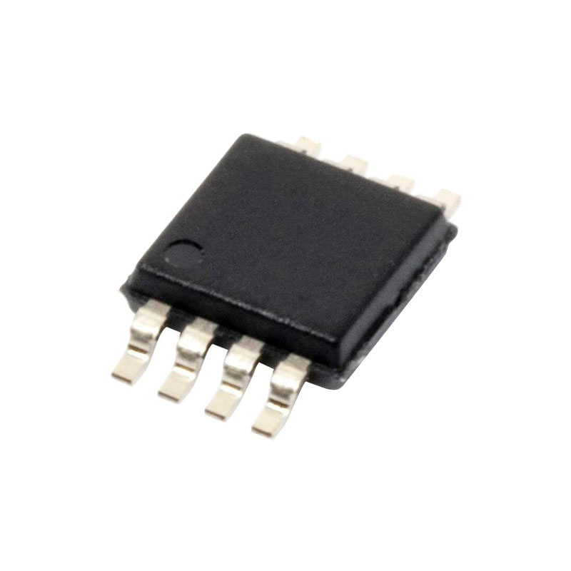
概要
AD627 は、シングル電源とデュアル電源(+2.2 V ~ ±18 V)で レール・ツー・レール出力スイングを実現する集積型マイクロ パワー計装アンプです。AD627 は、最大わずか 85 μA で動作しながら、優れた AC/DC 仕様を提供します。
AD627 は、8 リード業界標準ピンアウト構成に準拠しながら、外 部抵抗 1 つでデバイスのゲインを設定できる優れた柔軟性 を提供します。外部抵抗なしの場合、AD627 はゲイン 5 に設定されます。外 部抵抗を使用すると、最大 1000 のゲインに設定できます。
広い電源電圧範囲(+2.2 V ~ ±18 V)とマイクロパワー消費電流により、 AD627 は幅広いアプリケーションに最適です。単一電源動作、低消費電力、レール・ツー・レール出力スイングにより、AD627 はバッテリ駆動アプリケーションに理想的です。そのレール・ツー・レール出力段は、低電源電圧で動作するときのダイナミック・レンジを最大化します。デュアル電源動作(±15 V)と低消費電力により、AD627 は 4 mA ~ 20 mA のループ電源システムなどの産業用アプリケーションに最適です。
AD627 は、他のマイクロパワー計装アンプとは異なり、 性能を損なうことはありません。低電圧オフセット、オフセット・ドリフト、ゲイン・エラー、ゲイン・ドリフトはシステムの誤差を最小化します。AD627 はまた、周波数に対する優れた CMRR を提供することで、周波数に対する誤差も最小化します。CMRR は 200 Hz まで高いままなので、ライン・ノイズとライン高調波は除去されます。
AD627 は優れた性能を提供し、回路基板面積が少 なく、マイクロパワー・ディスクリート・デザインよりも低コ ストです。
特徴
マイクロパワー、最大供給電流85μA
広い電源範囲(+2.2 V~±18 V)
使いやすい
-外部抵抗1本でゲイン設定
-ゲインレンジ 5(抵抗なし)~1000
ディスクリート設計よりも高性能
レールツーレール出力スイング
高精度直流性能
-0.03% 標準ゲイン精度 (G = +5) (AD627A)
-10 ppm/°C 標準ゲイン・ドリフト(G = +5)
最大入力オフセット電圧 -125 μV (AD627B デュアル電源)
最大入力オフセット電圧 -200 μV (AD627A デュアル電源)
-最大入力オフセット電圧ドリフト (AD627B)
-最大入力オフセット電圧ドリフト (AD627A)
最大入力バイアス電流 -10 nA
ノイズ:38 nV/√Hz RTIノイズ(1 kHz)(G = +100
優れた交流仕様
-AD627A:最小CMRR 77 dB(G = +5)
-AD627B:最小CMRR 83 dB(G = +5)
-80 kHz帯域幅(G = +5)
0.01% までのセトリング時間 -135 μs (G = +5、5 V ステップ)
アプリケーション
4 mA~20 mAループ電源アプリケーション
低電力医療機器-ECG、EEG
トランスデューサーのインターフェース
熱電対アンプ
工業プロセス制御
低消費電力データ収集
携帯用電池式計器
動作理論
AD627は、2つのフィードバック・ループを使って作られた真のインスツルメンテーション・アンプです。その一般的な特性は、古典的な2オペアンプの計装アンプ構成に似ていますが、内部的には細部が多少異なります。AD627は、変更された電流フィードバック・スキームを使用し、段間フィードフォワード周波数補償と相まって、直流を超える周波数(特に50 Hzから60 Hzのライン周波数)において、低電力計装アンプに期待されるよりもはるかに優れた同相信号除去比(CMRR)を実現します。
リファレンス端子
基準端子電位はゼロ出力電圧を定義し、負荷がシステムの残りの部分と正確なグランドを共有していない場合に特に有用である。出力に正確なオフセットを注入する直接的な手段となる。基準端子はまた、バイポーラ信号を増幅する際にも、仮想的なグラウンド電圧を提供するため有用である。
AD627 の出力電圧はリファレンス端子の電位を基準にして発 生します;従って REF ピンを適切なローカル・グラウンドに接続す る事により、多くのグラウンドの問題が解決されます。最適な CMR のためには、REF ピンを低インピーダンスのポイントに 接続してください。


