概要
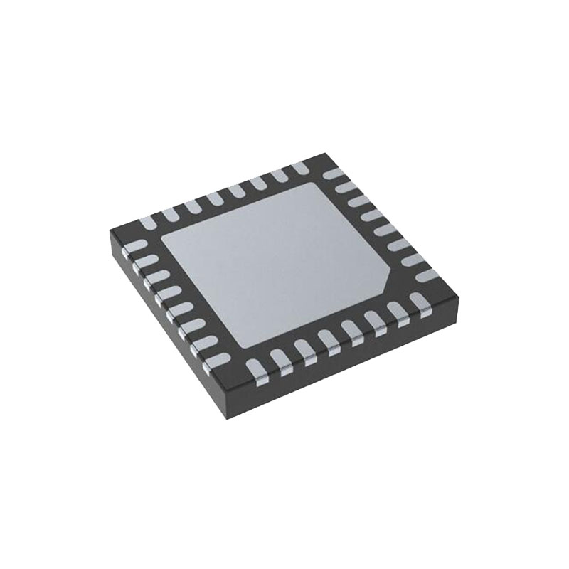
AD9634 は、最大 250 MSPS のサンプリング速度を持つ 12 ビット・アナログ・デジタ ル・コンバータ(ADC)です。AD9634 は、低コスト、小型、広帯域幅、汎用性が望まれる通信アプリケーションをサポートするように設計されています。ADC コアは、出力エラー訂正ロジックを内蔵した多段差動パイプラ イン・アーキテクチャを特徴としています。ADCは、ユーザーが選択可能な様々な入力範囲をサポートできる広帯域幅入力を特徴としています。統合された電圧リファレンスにより、設計の考慮が容易になります。デューティ・サイクル・スタビライザー(DCS)は、ADCクロックのデューティ・サイクルの変動を補正するために提供され、コンバーターが優れた性能を維持することを可能にします。ADC出力データは、外部12ビットLVDS出力ポートに直接配線されます。 セットアップと制御のためのプログラミングは、3 線式 SPI 互換シリアル・インターフェイスを使用して行います。AD9634 は 32 リード LFCSP で供給され、-40°C ~ +85°C の産業用温度範囲で仕様化されています。この製品は米国特許で保護されています。
製品ハイライト
- 内蔵12ビット、170 MSPS/210 MSPS/250 MSPS ADC。
- オーバーレンジとスレッショルドの高速検出。
- 独自の差動入力により、入力周波数350 MHzまで優れたSNR性能を維持。
- レジスタ・プログラミングおよびリードバック用3ピン、1.8 V SPIポート。
- AD9642とのピン互換性により、最大14ビットまでの簡単な移行が可能。
特徴
SNR = 69.7 dBFS(185 MHz AIN、250 MSPS時
SFDR = 87 dBc(185 MHz AIN、250 MSPS時
185 MHz、-1 dBFS AIN、250 MSPSでの入力ノイズ-150.6 dBFS/Hz
総消費電力:360 mW(250 MSPS時
1.8 V 電源電圧
LVDS(ANSI-644レベル)出力
整数1対8入力クロック分周器(最大入力625MHz)
最大250MSPSのサンプルレート
内部ADC電圧リファレンス
柔軟なアナログ入力範囲 1.4 V p-p~2.0 V p-p (公称1.75 V p-p)
ADCクロック・デューティ・サイクル・スタビライザー
シリアルポート制御
省エネパワーダウン・モード
アプリケーション
コミュニケーション
ダイバーシティ無線システム
マルチモード・デジタル・レシーバー(3G) TD-SCDMA、WiMAX、W-CDMA、CDMA2000、GSM、EDGE、LTE
I/Q復調システム
スマート・アンテナ・システム
汎用ソフトウェア無線機
超音波装置
ブロードバンド・データ・アプリケーション
動作理論
The AD9634 can sample any fS/2 frequency segment from dc to 250 MHz using appropriate low-pass or band-pass filtering at the ADC inputs with little loss in ADC performance. Programming and control of the AD9634 are accomplished using a 3-pin, SPI-compatible serial interface.
ADC ARCHITECTURE
The AD9634 architecture consists of a front-end sample-andhold circuit, followed by a pipelined, switched-capacitor ADC. The quantized outputs from each stage are combined into a final 12-bit result in the digital correction logic. The pipelined architecture permits the first stage to operate on a new input sample and the remaining stages to operate on the preceding samples. Sampling occurs on the rising edge of the clock. Each stage of the pipeline, excluding the last, consists of a low resolution flash ADC connected to a switched-capacitor digitalto-analog converter (DAC) and an interstage residue amplifier (MDAC). The MDAC magnifies the difference between the reconstructed DAC output and the flash input for the next stage in the pipeline. One bit of redundancy is used in each stage to facilitate digital correction of flash errors. The last stage simply consists of a flash ADC. The input stage contains a differential sampling circuit that can be ac- or dc-coupled in differential or single-ended modes. The output staging block aligns the data, corrects errors, and passes the data to the output buffers. The output buffers are powered from a separate supply, allowing digital output noise to be separated from the analog core. During power-down, the output buffers go into a high impedance state.
For more parameters, please refer to the Datasheets.


