概要
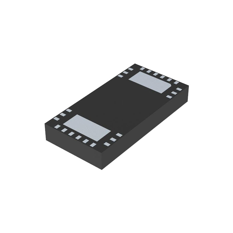
ADL5387は、30 MHz~2 GHzのRF/IF入力周波数範囲をカバーする広帯域直交I/Q復調器です。NF=13.2dB、IP1dB=12.7dBm、450MHzでのIIP3=32dBmのADL5387復調器は、要求の厳しいインフラストラクチャ・ダイレクト・コンバージョンの要件に適した優れたダイナミック・レンジを提供します。差動RF/IF入力は、50Ωの良好な広帯域入力インピーダンスを提供し、最適な性能を得るために1:1バランから駆動するのが最適です。 超広帯域動作は、局部発振器(LO)の直交信号生成に2分周方式を採用することで達成される。広範囲のLOレベルにおいて、振幅と位相のバランスはそれぞれ~0.05dBと~0.4°で、優れた復調精度が達成されている。復調された同相(I)および直交(Q)差動出力は完全にバッファされ、4 dBを超える電圧変換利得を提供する。バッファリングされたベースバンド出力は、2 V p-p 差動信号を200 Ωに駆動することが可能です。完全バランス設計により、2次歪みの影響を最小限に抑えています。LOポートからRFポートへのリークは70dBc未満です。I出力とQ出力の差動DCオフセットは 60 dBm に寄与しています。 ADL5387 は 4.75 V ~ 5.25 V の単一電源で動作します。電源電流は BIAS ピンからグランドへの外付け抵抗で調整可能です。ADL5387 は、アナログ・デバイセズ社の先進的なシリコン・ゲルマニウム・バイポーラ・プロセスで製造され、24 リード露出パドル LFCSP で供給されます。
特徴
動作RF周波数 30 MHz~2 GHz
LO入力(2 × fLO) 60 MHz~4 GHz
入力IP3:900 MHzで31 dBm
入力IP2:900MHzで62dBm
入力P1dB: 900 MHzで13 dBm
雑音指数(NF) 12.0 dB(140 MHz) 14.7 dB(900 MHz
電圧変換利得 > 4 dB
直交復調精度 位相精度 ~0.4° 振幅バランス ~0.05 dB
復調帯域幅 ~240 MHz
ベースバンドI/Qドライブ 2 V p-p(200 Ω
5V単一電源
アプリケーション
QAM/QPSK RF/IF復調器
W-CDMA/CDMA/CDMA2000/GSM
マイクロ波ポイント・ツー・(マルチ)ポイント無線機
ブロードバンドワイヤレスとWiMAX
ブロードバンドCATV
アプリケーション情報
電源
The nominal voltage supply for the ADL5387 is 5 V and is applied to the VPA, VPB, VPL, and VPX pins. Ground should be connected to the COM, CML, and CMRF pins. Each of the supply pins should be decoupled using two capacitors; recommended capacitor values are 100 pF and 0.1 µF. LOCAL OSCILLATOR (LO) INPUT The LO port is driven in a single-ended manner. The LO signal must be ac-coupled via a 1000 pF capacitor directly into LOIP, and LOIN is ac-coupled to ground also using a 1000 pF capacitor. The LO port is designed for a broadband 50 Ω match and therefore exhibits excellent return loss from 60 MHz to 4 GHz.The recommended LO drive level is between −6 dBm and +6 dBm. For operation below 50 MHz, a minimum LO drive level of 0 dBm should be used. The LO frequency at the input to the device should be twice that of the desired LO frequency at the mixer core. The applied LO frequency range is between 60 MHz and 4 GHz.
RF入力
The RF inputs have a differential input impedance of approximately 50 Ω. For optimum performance, the RF port should be driven differentially through a balun. The recommended balun is M/A-COM ETC1-1-13. The RF inputs to the device should be ac-coupled with 1000 pF capacitors. Ground-referenced choke inductors must also be connected to RFIP and RFIN (recommended value = 120 nH, Coilcraft 0402CS-R12XJL) for appropriate biasing. Several important aspects must be taken into account when selecting an appropriate choke inductor for this application. First, the inductor must be able to handle the approximately 40 mA of standing dc current being delivered from each of the RF input pins (RFIP, RFIN). (The suggested 0402 inductor has a 50 mA current rating). The purpose of the choke inductors is to provide a very low resistance dc path to ground and high ac impedance at the RF frequency so as not to affect the RF input impedance. A choke inductor that has a selfresonant frequency greater than the RF input frequency ensures that the choke is still looking inductive and therefore has a more predictable ac impedance (jωL) at the RF frequency.


