GENERAL DESCRIPTION
The ADM7160 is an ultralow noise, low dropout linear regulator that operates from 2.2 V to 5.5 V and provides up to 200 mA of output current. The low 150 mV dropout voltage at 200 mA load improves efficiency and allows operation over a wide input voltage range. Using an innovative circuit topology, the ADM7160 achieves ultralow noise performance without the need for a bypass capacitor, making the device ideal for noise-sensitive analog front-end and RF applications. The ADM7160 also achieves ultralow noise performance without compromising PSRR or transient line and load performance. Current-limit and thermal overload protection circuits prevent damage under adverse conditions. The ADM7160 also includes an internal pull-down resistor on the EN input.The ADM7160 is specifically designed for stable operation with tiny 1 µF, ±30% ceramic input and output capacitors to meet the requirements of high performance, space constrained applications. The ADM7160 is available in tiny 5-lead TSOT and 6-lead LFCSP packages with 16 fixed output voltage options, ranging from 1.1 V to 3.3 V. The LFCSP offers a very compact solution that provides excellent thermal performance for applications that require up to 200 mA of output current in a small, low profile footprint.
FEATURES
PSRR performance of 54 dB at 100 kHz
Ultralow noise independent of VOUT 3 µV rms, 0.1 Hz to 10 Hz 9.5 µV rms, 0.1 Hz to 100 kHz 9 µV rms, 10 Hz to 100 kHz 17 µV rms, 10 Hz to 1 MHz
Low dropout voltage: 150 mV at 200 mA load
Maximum output current: 200 mA
Input voltage range: 2.2 V to 5.5 V
Low quiescent and shutdown current
Initial accuracy: ±1%
Accuracy over line, load, and temperature: −2.5%/+1.5%
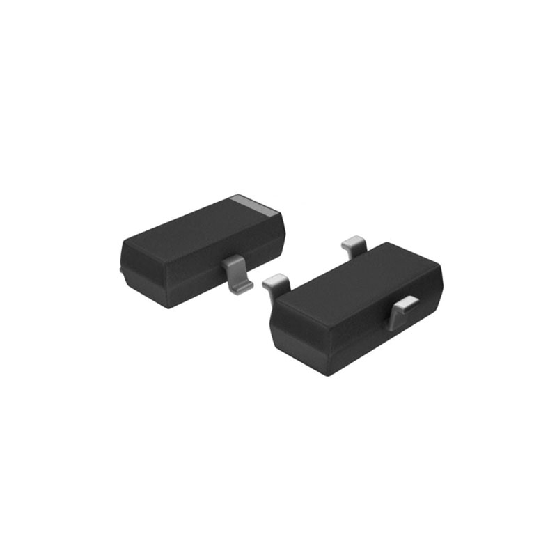
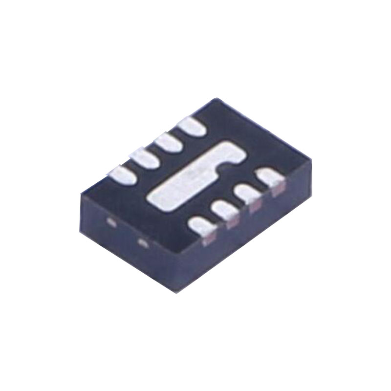
5-lead TSOT package and 6-lead LFCSP package
APPLICATIONS
ADC/DAC power supplies
RF, VCO, and PLL power supplies
Post dc-to-dc regulation
APPLICATIONS INFORMATION
CAPACITOR SELECTION
Output Capacitor
The ADM7160 is designed for operation with small, space-saving ceramic capacitors, but it can function with most commonly used capacitors as long as care is taken with regard to the effective series resistance (ESR) value. The ESR of the output capacitor affects the stability of the LDO control loop. A minimum of 1 μF capacitance with an ESR of 1 Ω or less is recommended to ensure the stability of the ADM7160. Transient response to changes in load current is also affected by output capacitance. Using a larger value of output capacitance improves the transient response of the ADM7160 to large changes in load current.
Input Bypass Capacitor
Connecting a 1 μF capacitor from VIN to GND reduces the circuit sensitivity to the PCB layout, especially when long input traces or high source impedance are encountered. If output capacitance greater than 1 μF is required, the input capacitor should be increased to match it.
Input and Output Capacitor Properties
Any good quality ceramic capacitor can be used with the ADM7160, as long as it meets the minimum capacitance and maximum ESR requirements. Ceramic capacitors are manufactured with a variety of dielectrics, each with different behavior over temperature and applied voltage. Capacitors must have an adequate dielectric to ensure the minimum capacitance over the required temperature range and dc bias conditions. X5R or X7R dielectrics with a voltage rating of 6.3 V or 10 V are recommended. Y5V and Z5U dielectrics are not recommended, due to their poor temperature and dc bias characteristics.
THERMAL CONSIDERATIONS
In most applications, the ADM7160 does not dissipate much heat due to its high efficiency. However, in applications with high ambient temperature and a high supply voltage-to-output voltage differential, the heat dissipated in the package can cause the junction temperature of the die to exceed the maximum junction temperature of 125°C. When the junction temperature exceeds 150°C, the ADM7160 enters thermal shutdown. To prevent any permanent damage, the regulator recovers only after the junction temperature decreases below 135°C. Therefore, thermal analysis for the selected application is very important to guarantee reliable performance over all conditions. The junction temperature of the die is the sum of the ambient temperature of the environment and the temperature rise of the package due to the power dissipation, as shown in Equation 2.To guarantee reliable operation, the junction temperature of the ADM7160 must not exceed 125°C. To ensure that the junction temperature stays below this maximum value, the user must be aware of the parameters that contribute to junction temperature changes. These parameters include ambient temperature, power dissipation in the power device, and thermal resistance between the junction and ambient air (θJA). The θJA value is dependent on the package assembly compounds used and the amount of copper used to solder the package GND pin and the exposed pad (in the case of the LFCSP) to the PCB.