DESCRIPTION
The LT4321 is a dual ideal diode bridge controller that enables a Power over Ethernet (PoE) powered device (PD) to receive power in either voltage polarity from RJ-45 data pairs, spare pairs, or both. The LT4321 and eight N-channel MOSFETs replace the eight diodes in a passive PoE rectifier bridge. The LT4321 eases thermal design and increases delivered power.
An internal charge pump allows an all-NMOS bridge eliminating larger and more costly PMOS switches. The LT4321 works with 2-pair and 4-pair applications. High impedance input sense pins prevent reverse current on unused pairs. If the power source fails or is shorted, a fast turn-off minimizes reverse current transients. Unlike discrete ideal bridge solutions, the LT4321 will operate through transients without enabling the MOSFETs on unpowered pairs.
FEATURES
Reduces Heat, Eliminates Thermal Design Problems
Maximizes Power Efficiency
Less than 800µA Quiescent Operating Current
Fully Compatible with IEEE 802.3af/at/bt Detection and Classification
IEEE 802.3af/at/bt Compliant When Paired with a Powered Device (PD) Controller
Works with 2-Pair and 4-Pair PoE Applications
Compatible with PoE, PoE+, PoE++, and LTPoE++®
100V Absolute Maximum Voltage
H-Grade Version Operates Up to 125°C
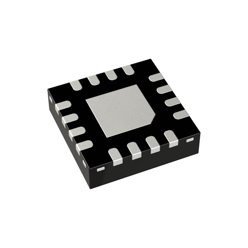
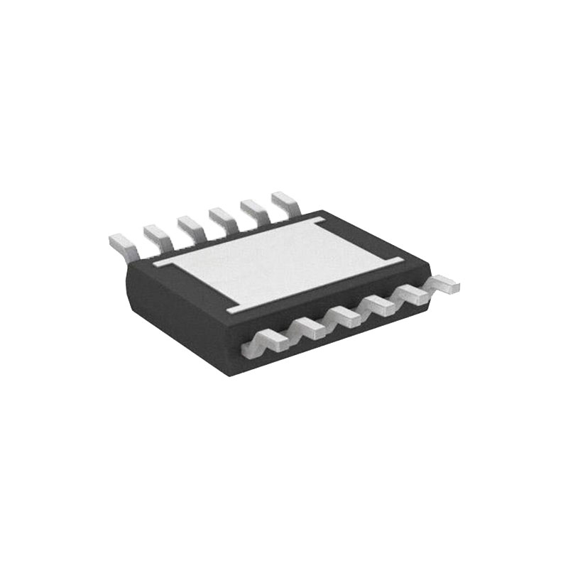
16-Lead 4mm × 4mm QFN Package
APPLICATIONS
PoE/PoE+/PoE++/LTPoE++ Powered Devices
DC Polarity Correction and Ideal Diode-ORing of Telecom Supplies
APPLICATIONS INFORMATION
OVERVIEW
The LT4321 is a dual ideal diode bridge controller designed to rectify two independent DC channels into a single output. An LT4321-based solution meets IEEE 802.3 PoE requirements for a PD diode bridge and rectifies both 2-pair and 4-pair power from an Ethernet cable into a common output. The LT4321 senses the greater of the two input channels, |IN12-IN36| or |IN45-IN78|, and connects them to the output with the correct polarity. Smooth crossover between channels is guaranteed by the enforced dropout voltage, ∆VSD.
The LT4321 uses actively driven MOSFETs to nearly elimi-nate the forward voltage drop. By maximizing available voltage and reducing power dissipation, the LT4321 simplifies PD design and reduces power supply cost. It can also eliminate thermal design problems, costly heat sinks, and reduce PC board area.
The LT4321 offers significant improvements over discrete solutions. The integrated bridge controller allows for sophisticated sensing and control of the PowerPath™ MOSFETs, ensuring that MOSFETs that are supposed to be off, stay off. An ideal bridge controlled by the LT4321 is tolerant to hot-plugs, input shortcircuits, common mode shift, and PCB leakage in the application circuit.
OPERATING MODES
Ideal Diode Bridge Mode
In ideal bridge mode the LT4321 saves power by activating MOSFETs in place of power path diodes. The LT4321 enters ideal bridge mode when OUTP is greater than VUVLO and either EN or EN is asserted.
When the LT4321 is enabled, it senses the inputs with respect to the output to decide which external MOSFETs to turn on. Inputs are grouped into pairs, IN12/IN36 and IN45/IN78. Within each pair, one input voltage must be greater than OUTP and one must be less than OUTN before the external MOSFETs related to that pair are enabled.
Shutdown Mode
Shutdown mode is intended to keep the LT4321 quiescent current from interfering with detection and classification in a PoE system. The LT4321 is always in shutdown mode when OUTP < VUVLO. It can be held in shutdown mode over the full operating voltage range by deasserting both the EN and EN pins.
Shutting down the LT4321 does not disconnect the load. The external MOSFETs are shorted gate to source and bridge current is carried by the MOSFETs’ body diodes. The eight body diodes will act like two traditional diode bridges. At light load, the power dissipated in the forward drop of the body diodes will be less than the power dissipated by the LT4321 quiescent current. In applications with a low power sleep mode, the LT4321 can optionally be shut down to save power if the load current is less than 20mA.

