DESCRIPTION
The LTC3115-1 is a high voltage monolithic synchronous buck-boost DC/DC converter. Its wide 2.7V to 40V input and output voltage ranges make it well suited to a wide variety of automotive and industrial applications. A proprietary low noise switching algorithm optimizes efficiency with input voltages that are above, below or even equal to the output voltage and ensures seamless transitions between operational modes. Programmable frequency PWM mode operation provides low noise, high efficiency operation and the ability to synchronize switching to an external clock. Switching frequencies up to 2MHz are supported to allow use of small value inductors for miniaturization of the application circuit. Pin selectable Burst Mode operation reduces standby current and improves light load efficiency which, combined with a 3µA shutdown current, make the LTC3115-1 ideally suited for battery-powered applications. Additional features include output disconnect in shutdown, short-circuit protection and internal soft-start. The LTC3115-1 is available in thermally enhanced 16-lead 4mm × 5mm × 0.75mm DFN and 20-lead TSSOP packages.
FEATURES
Wide VIN Range: 2.7V to 40V
Wide VOUT Range: 2.7V to 40V
1A Output Current for VIN ≥ 3.6V, VOUT = 5V
2A Output Current in Step-Down Operation for VIN ≥ 6V
Programmable Frequency: 100kHz to 2MHz
Synchronizable Up to 2MHz with an External Clock
Up to 95% Efficiency
30µA No-Load Quiescent Current in Burst Mode® Operation
Ultralow Noise Buck-Boost PWM
Internal Soft-Start
3µA Supply Current in Shutdown
Programmable Input Undervoltage Lockout
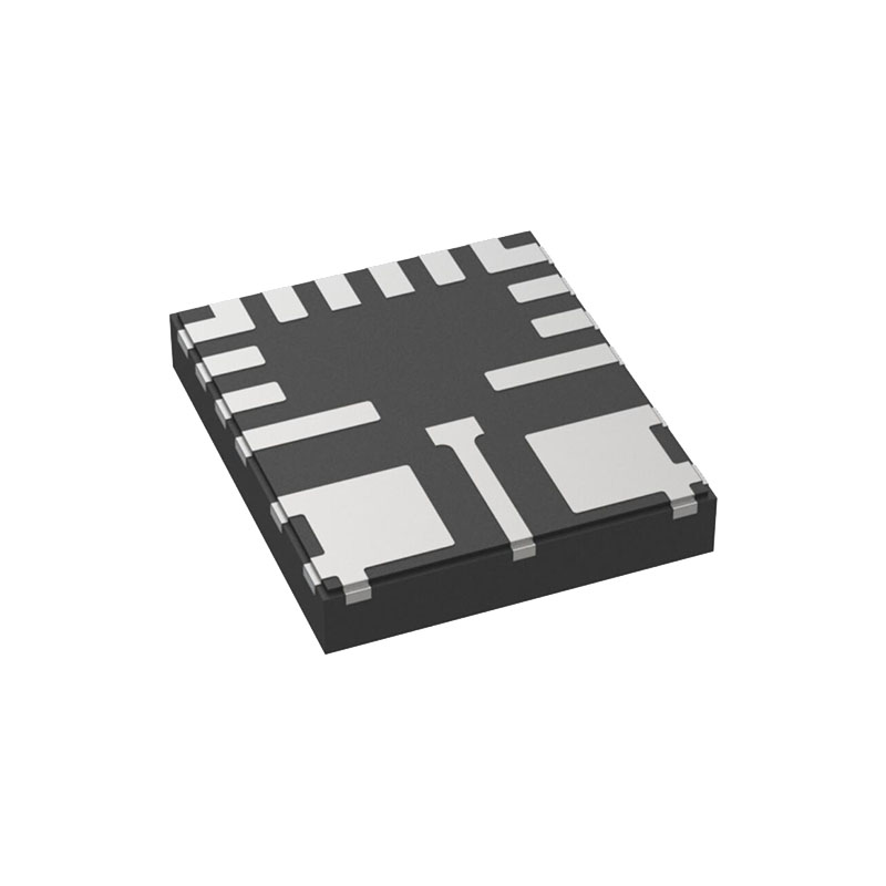
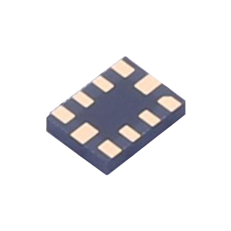
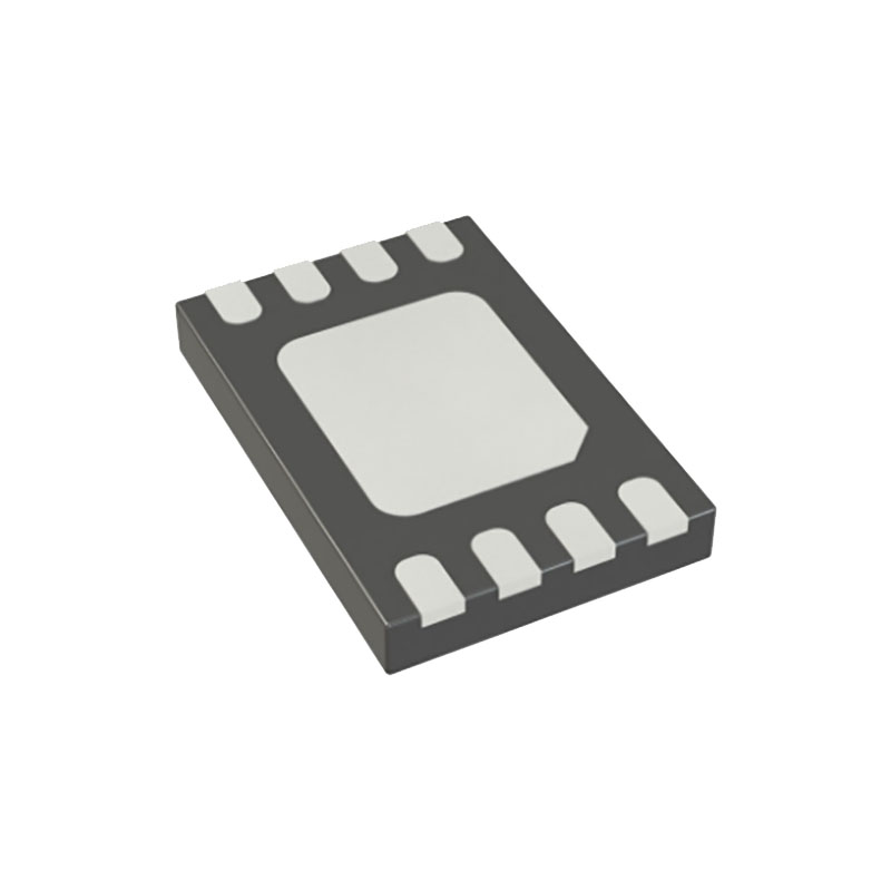
Small 4mm × 5mm × 0.75mm DFN Package
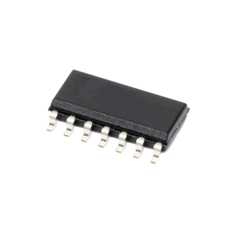
Thermally Enhanced 20-Lead TSSOP Package
AEC-Q100 Qualified for Automotive Applications
APPLICATIONS
24V/28V Industrial Applications
Automotive Power Systems
Telecom, Servers and Networking Equipment
FireWire Regulator
Multiple Power Source Supplie
APPLICATIONS INFORMATION
The standard LTC3115-1 application circuit is shown as the typical application on the front page of this data sheet. The appropriate selection of external components is dependent upon the required performance of the IC in each particular application given considerations and trade-offs such as PCB area, cost, output and input voltage, allowable ripple voltage, efficiency and thermal considerations. This section of the data sheet provides some basic guidelines and considerations to aid in the selection of external components and the design of the application circuit.
VCC Capacitor Selection
The VCC output on the LTC3115-1 is generated from the input voltage by an internal low dropout regulator. The VCC regulator has been designed for stable operation with a wide range of output capacitors. For most applications, a low ESR ceramic capacitor of at least 4.7µF should be utilized. The capacitor should be placed as close to the pin as possible and should connect to the PVCC pin and ground through the shortest traces possible. The PVCC pin is the regulator output and is also the internal supply pin for the gate drivers and boost rail charging diodes. The VCC pin is the supply connection for the remainder of the control circuitry. The PVCC and VCC pins must be connected together on the application PCB. If the trace connecting VCC to PVCC cannot be made via a short connection, an additional 0.1µF bypass capacitor should be placed between the VCC pin and ground using the shortest connections possible.
Inductor Selection
The choice of inductor used in LTC3115-1 application circuits influences the maximum deliverable output current, the magnitude of the inductor current ripple, and the power conversion efficiency. The inductor must have low DC series resistance or output current capability and efficiency will be compromised. Larger inductance values reduce inductor current ripple and will therefore generally yield greater output current capability. For a fixed DC resistance, a larger value of inductance will yield higher efficiency by reducing the peak current to be closer to the average output current and therefore minimize resistive losses due to high RMS currents. However, a larger inductor value within any given inductor family will generallyhave a greater series resistance, thereby counteracting this efficiency advantage. In general, inductors with larger inductance values and lower DC resistance will increase the deliverable output current and improve the efficiency of LTC3115-1 applications.