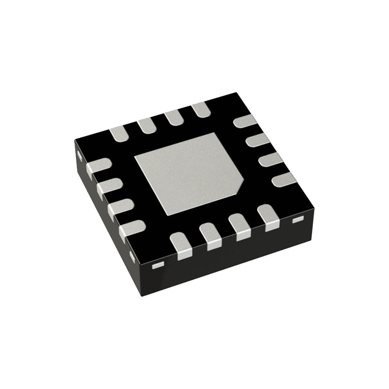
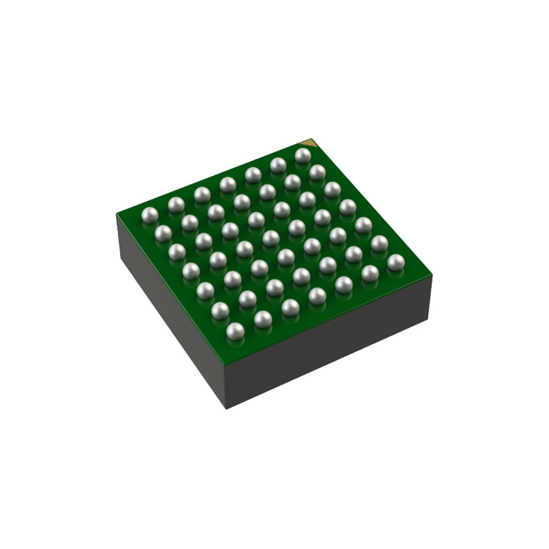
Description
The Texas Instruments MSP430™ family of ultra-low-power microcontrollers (MCUs) consist of several devices featuring different sets of peripherals targeted for various applications. The architecture, combined with five low-power modes is optimized to achieve extended battery life in portable measurement applications. The device features a powerful 16-bit RISC CPU, 16-bit registers, and constant generators that attribute to maximum code efficiency. The digitally controlled oscillator (DCO) allows wake-up from low-power modes to active mode in less than 6 µs.
The MSP430F13x, MSP430F14x, and MSP430F14x1 MCUs support two built-in 16-bit timers, a fast 12-bit ADC on the MSP430F13x and the MSP430F14x devices, one USART on the MSP430F13x devices or two USARTs on the MSP430F14x and MSP430F14x1 devices, and 48 I/O pins. The hardware multiplier enhances the performance and offers a broad code and hardware-compatible family solution.
Features
• LowSupply Voltage Range, 1.8 V to 3.6 V
• Ultra-Low Power Consumption:
– Active Mode: 280 µA at 1 MHz, 2.2 V
– Standby Mode: 1.6 µA
– Off Mode (RAM Retention): 0.1 µA
• Five Power-Saving Modes
• Wakeup From Standby Mode in Less Than 6 µs
• 16-Bit RISC Architecture, 125-ns Instruction Cycle Time
• 12-Bit Analog-to-Digital Converter (ADC) With Internal Reference, Sample-and-Hold, and Autoscan Feature
• 16-Bit Timer_B With Seven Capture/Compare With-Shadow Registers
• 16-Bit Timer_A With Three Capture/Compare Registers
• On-Chip Comparator
• Serial Onboard Programming, No External Programming Voltage Needed, Programmable Code Protection by Security Fuse
• Serial Communication Interface (USART), Functions as Asynchronous UART or Synchronous
SPI Interface
– TwoUSARTs (USART0, USART1) On MSP430F14x and MSP430F14x1 Devices
– OneUSART(USART0) On MSP430F13x Devices
• Family Members (Also See Device Comparison)
– MSP430F133
– 8KB+256 Bytes of Flash Memory, 256 Bytes of RAM
– MSP430F135
– 16KB +256 Bytes of Flash Memory, 512 Bytes of RAM
– MSP430F147, MSP430F1471
– 32KB +256 Bytes of Flash Memory, 1KB of RAM
– MSP430F148, MSP430F1481
– 48KB +256 Bytes of Flash Memory, 2KB of RAM
– MSP430F149, MSP430F1491
– 60KB +256 Bytes of Flash Memory, 2KB of RAM
Applications
• Sensor Systems
• Industrial Controls
• Hand-Held Meters
CPU
The MSP430 CPU has a 16-bit RISC architecture that is highly transparent to the application. All operations, other than program-flow instructions, are performed as register operations in conjunction with seven addressing modes for source operand and four addressing modes for destination operand.
The CPU is integrated with 16 registers that provide reduced instruction execution time. The register-to-register operation execution time is one cycle of the CPU clock. Four of the registers, R0 to R3, are dedicated as program counter, stack pointer, status register, and constant generator, respectively. The remaining registers are general-purpose registers. Peripherals are connected to the CPU using data, address, and control buses, and can be handled with all instructions.
The instruction set consists of the original 51 instructions with three formats and seven address modes and additional instructions for the expanded address range. Each instruction can operate on word and byte data.
JTAGFuse Check Mode
MSP430 MCUs that have the fuse on the TDI/TCLK terminal have a fuse check mode that tests the continuity of the fuse the first time the JTAG port is accessed after a power-on reset (POR). When activated, a fuse check current (ITF) of 1 mA at 3 V or 2.5 mA at 5 V can flow from the TDI/TCLK pin to ground if the fuse is not burned. Care must be taken to avoid accidentally activating the fuse check mode and increasing overall system power consumption.
Activation of the fuse check mode occurs with the first negative edge on the TMS pin after power up or if the TMS is being held low during power up. The second positive edge on the TMS pin deactivates the fuse check mode. After deactivation, the fuse check mode remains inactive until another POR occurs. After each POR the fuse check mode has the potential to be activated.
The fuse check current flows only when the fuse check mode is active and the TMS pin is in a low state. Therefore, the additional current flow can be prevented by holding the TMS pin high (default condition).


