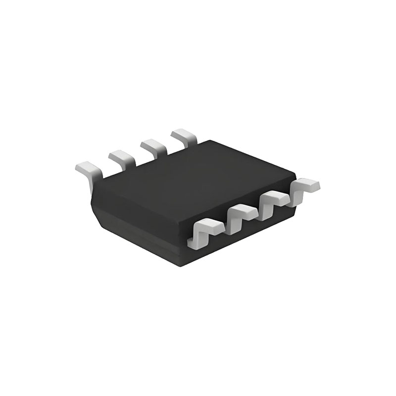
ОПИСАНИЕ
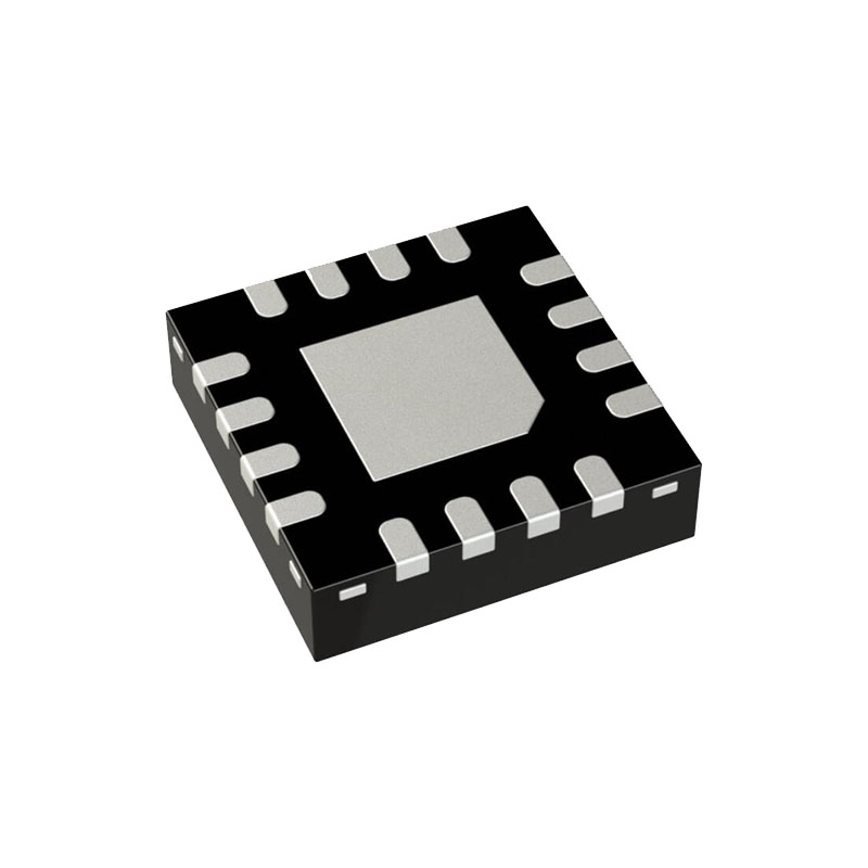
The LT3482 is a fixed frequency current mode step-up DC/DC converter with voltage doubler designed to bias avalanche photodiodes (APDs) in optical receivers. It can provide up to 90V output. The LT3482 features high side APD current monitoring with better than 10% relative accuracy over the entire temperature range. The integrated power switch, Schottky diodes and APD current monitor allow a small converter footprint and low solution cost. Constant switching frequency results in predictable output noise that is easy to filter. The inductor-based topology ensures an input free from switching noise. An integrated high side current monitor produces a current proportional to APD current with better than 10% relative accuracy over four decades of dynamic range in the input range of 250nA to 2.5mA. This current can be used as a reference to provide a digitally programmed output voltage via the CTRL pin. The LT3482 is available in the tiny footprint (3mm × 3mm) 16-lead QFN package.
ОСОБЕННОСТИ
High Output Voltage: Up to 90V
Integrated Schottky Diodes
48V, 280mA Internal Switch
High Side APD Current Monitor
Adjustable Switching Frequency: 650kHz or 1.1MHz
Wide VIN Range: 2.5V to 16V
Компоненты для поверхностного монтажа
Низкий ток выключения: <1 мкА
Мягкий старт
Внутренняя компенсация
Вывод CTRL позволяет регулировать выход без инверсии полярности
16-выводной пакет QFN 3 мм × 3 мм
ПРИЛОЖЕНИЯ
Предвзятое отношение к APD
Подводка PIN-диода
Оптические приемники и модули
Оборудование для оптоволоконных сетей
ОПЕРАЦИЯ
The LT3842 boost converter uses a constant frequency current mode control scheme to provide excellent line and load regulation. At the start of each oscillator cycle, the SR latch is set, which turns on the power switch, Q1. A voltage proportional to the switch current is added to a stabilizing ramp and the resulting sum is fed into the positive terminal of the PWM comparator, A2. When this voltage exceeds the level at the negative input of A2, the SR latch is reset turning off the power switch. The level at the negative input of A2 is set by the error amplifier A1, and is simply an amplified version of the difference between the feedback voltage and the reference voltage of 1.235V, or externally provided CTRL voltage. In this manner, the error amplifier sets the correct peak current level to keep the output in regulation. If the error amplifier’s output increases, more current is delivered to the output; if it decreases, less current is delivered.
The LT3482 has an integrated high side APD current monitor with a 5:1 ratio. The MONIN pin can accept a supply voltage up to 90V, which is suitable for APD photodiode applications. The MON pin has an open-circuit protection feature and is internally clamped to 11.5V.
If an APD is tied to the APD pin, the current will be mirrored to the MON pin and converted to a voltage signal by the resistor R3. This voltage signal can be used to drive an external control block to adjust the APD voltage by adjusting the feedback threshold of EAMP A1 through the CTRL input.
ИНФОРМАЦИЯ О ПРИЛОЖЕНИЯХ
Частота переключения
The LT3482 can operate at either 650kHz nominal or 1.1MHz nominal; the voltage at the fSET pin selects which frequency is used. At 1.1MHz, a physically smaller inductor and capacitor can be used in a given application, but higher frequencies will slightly decrease efficiency and maximum duty cycle. Generally if efficiency and maximum duty cycle are crucial, the lower switching frequency should be selected by connecting fSET to GND. If application size and cost are more important, connect fSET to VIN to select the higher switching frequency.
Setting Output Voltage
The LT3482 is equipped with both an internal 1.235V reference and an auxiliary reference input (the CTRL pin). This allows users to select between using the built-in reference and supplying an external reference voltage. The voltage at the CTRL pin can be adjusted while the chip is operating to alter the output voltage of LT3482 for purposes such as APD’s bias voltage adjustment. To use the internal 1.235V reference, the CTRL pin should be held higher than 1.5V, which can be done by tying it to VIN. When the CTRL pin is between 0V and 1.2V, the LT3482 will regulate the output such that the FB pin voltage is equal to the CTRL pin voltage.

