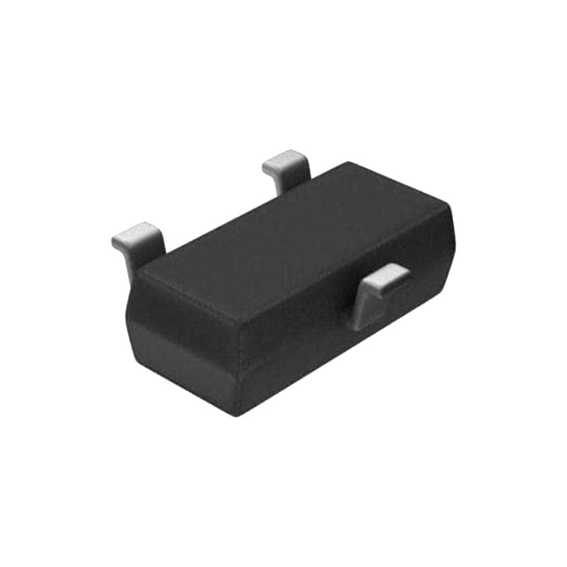
ОПИСАНИЕ
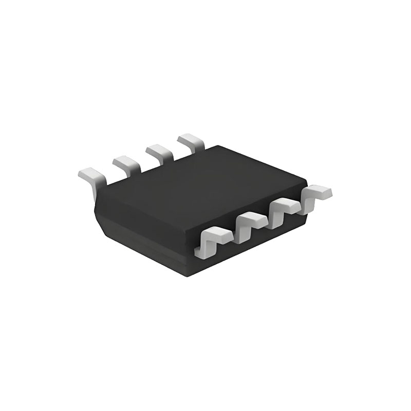
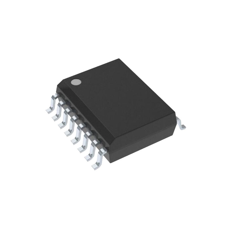
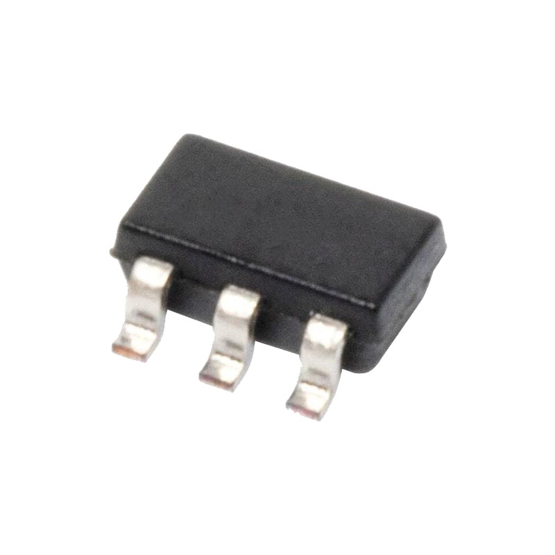
LTC4211 - это контроллер горячей замены, который позволяет безопасно вставлять и извлекать плату из объединительной панели под напряжением. Внутренний драйвер переключателя высокой стороны управляет затвором внешнего N-канального MOSFET при напряжении питания от 2,5 В до 16,5 В. LTC4211 обеспечивает плавный пуск и ограничение пускового тока в течение периода запуска, который имеет программируемую продолжительность.
Two on-chip current limit comparators provide dual level overcurrent circuit breaker protection. The slow comparator trips at VCC – 50mV and activates in 20μs (or is programmed by an external filter capacitor, MS only). The fast comparator trips at VCC – 150mV and typically responds in 300ns.
The FB pin monitors the output supply voltage and signals the RESET output pin. The ON pin signal turns the chip on and off and can also be used for the reset function. The MS package has FAULT and FILTER pins to provide additional functions like fault indication, autoretry or latch-off modes, programmable current limit response time and programmable overvoltage protection using an external Zener diode clamp.
ОСОБЕННОСТИ
Allows Safe Board Insertion and Removal from a Live Backplane
Напряжение питания от 2,5 В до 16,5 В
Программируемый плавный пуск с ограничением пускового тока, не требующий внешнего конденсатора затвора
Faster Turn-Off Time Because No External Gate Capacitor is Required
Двухуровневая защита от перегрузки по току
Programmable Response Time for Overcurrent Protection (MS)
Программируемая защита от перенапряжения (MS)
Автоматический повтор или работа в режиме задержки (MS)
Привод высокой стороны для внешнего N-канального транзистора
Программируемое пользователем напряжение питания Скорость включения
Вывод FB Контролирует выходной сигнал VOUT и сигнализирует о сбросе RESET
Glitch Filter Protects Against Spurious RESET Signal
ПРИЛОЖЕНИЯ
Электронный автоматический выключатель
Hot Board Insertion and Removal (Either On Backplane or On Removable Card)
Промышленные выключатели/прерыватели с высокой боковой стенкой
ОПЕРАЦИЯ
ВСТАВКА ГОРЯЧЕГО КОНТУРА
Когда печатные платы вставляются или извлекаются из объединительных плат под напряжением, шунтирующие конденсаторы питания могут потреблять огромные переходные токи от шины питания объединительной платы при их зарядке. Переходный ток может привести к необратимому повреждению контактов разъема, а также вызвать сбои в питании системы, что приведет к перезагрузке других плат в системе.
LTC4211 предназначен для контролируемого включения и выключения питающих напряжений печатной платы, что позволяет безопасно вставлять или извлекать плату из щита под напряжением. Устройство обеспечивает сигнал сброса системы, сигнализирующий о падении напряжения питания платы ниже заданного уровня, а также двухфункциональный монитор неисправностей.
КОНТРОЛЬ ВЫХОДНОГО НАПРЯЖЕНИЯ
The LTC4211 uses a 1.236V bandgap reference, precision voltage comparator and an external resistive divider to monitor the output supply voltage.
The operation of the supply monitor in normal mode is illustrated in Figure 2. When the voltage at the FB pin drops below its reset threshold (1.236V), the comparator COMP2 output goes high. After a glitch filter delay, RESET is pulled low (Time Point 1). When the voltage at the FB pin rises above its reset threshold (1.239V), COMP2’s output goes low and a timing cycle starts (Time Point 4). After a complete timing cycle, RESET is pulled high by the external pull-up resistor. If the FB pin rises above the reset threshold for less than a timing cycle, the RESET output remains low (Time Points 2 to 3).
The LTC4211’s RESET pin is logic low during any undervoltage lockout condition and during the initial insertion of a PC board. Under normal operation, RESET goes to logic high at the end of the soft-start cycle only after the FB pin voltage rises above its reset threshold of 1.239V.
БЛОКИРОВКА ПРИ ПОНИЖЕННОМ НАПРЯЖЕНИИ
Схема сброса при включении питания LTC4211 инициализирует процедуру запуска и гарантирует, что микросхема находится в надлежащем состоянии, если входное напряжение питания слишком низкое. Если напряжение питания падает ниже 2,18 В, LTC4211 переходит в режим блокировки по пониженному напряжению (UVLO), а вывод GATE подтягивается к низкому уровню. Поскольку в схеме UVLO используется гистерезис, микросхема перезапускается после того, как напряжение питания поднимается выше 2,3 В и вывод ON становится высоким.
In addition, users can utilize the ON comparator (COMP1) or the FAULT comparator (COMP6) to effectively program a higher undervoltage lockout level. Figure 3 shows how the external resistive divider at the ON pin programs the system’s undervoltage lockout voltage. The system will enter the plug-in cycle after the ON pin rises above 1.316V. The resistive divider sets the circuit to turn on when VCC reaches around 79% of its final value. If a different turn on VCC voltage is desired change the resistive divider values accordingly. Alternatively, the FAULT comparator can be used to configure the external undervoltage lockout level. If the FAULT comparator is used for this purpose, the system will wait for the input voltage to increase above the level set by the user before starting the second timing cycle. Also, if the input voltage drops below the set level in normal operating mode, the user must cycle the ON pin or VCC to restart the system.

