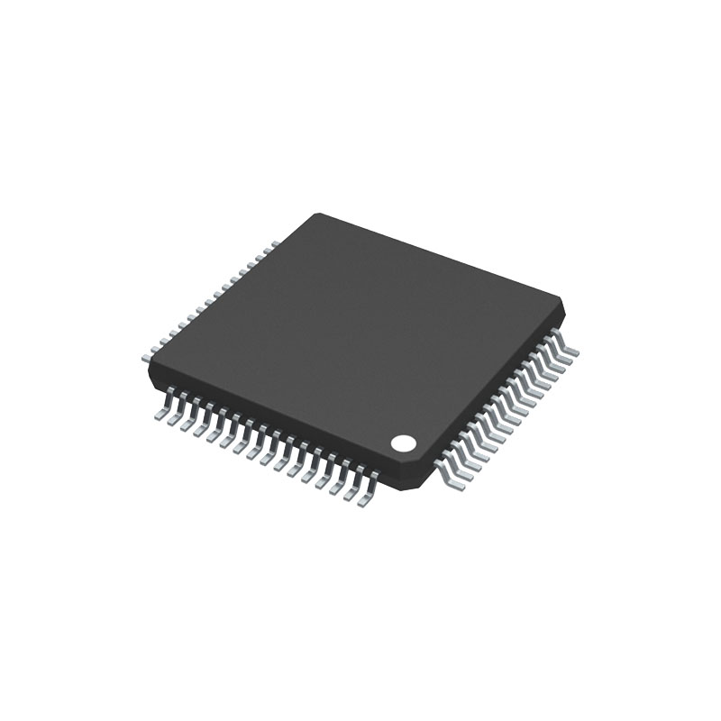
Описание
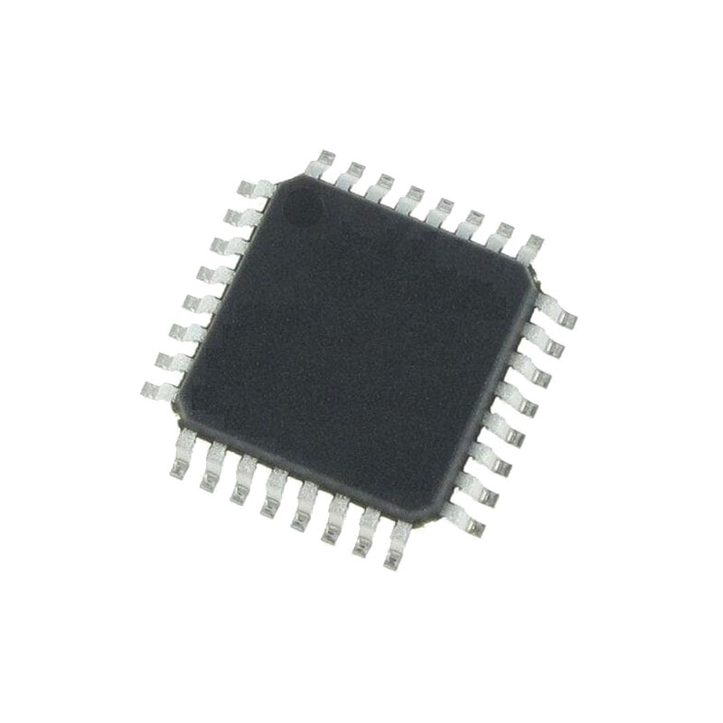
8-разрядные микроконтроллеры STM8S903K3/F3 линейки доступа предлагают 8 Кбайт флэш-памяти для программ, а также встроенную истинную память данных EEPROM. В справочном руководстве по семейству микроконтроллеров STM8S (RM0016) устройства этого семейства названы устройствами низкой плотности. Они обеспечивают следующие преимущества: производительность, надежность и снижение стоимости системы.
Производительность и надежность устройства обеспечивается передовым ядром и периферийными устройствами, выполненными по современной технологии, тактовой частотой 16 МГц, надежными входами/выходами, независимыми сторожевыми устройствами с отдельным источником тактовой частоты и системой защиты тактовой частоты.
Стоимость системы снижается благодаря встроенному EEPROM с истинными данными, рассчитанному на 300 тыс. циклов записи/стирания, и высокому уровню интеграции системы с внутренними тактовыми генераторами, сторожевым таймером и сбросом при отключении питания.
Предлагается полная документация, а также широкий выбор инструментов разработки.
Характеристики
Ядро
- Усовершенствованное ядро STM8 с частотой 16 МГц, гарвардской архитектурой и трехступенчатым конвейером
- Расширенный набор инструкций
Воспоминания
- Память программ: 8 Кбайт флэш-памяти; срок хранения данных 20 лет при 55 °C после 10 кциклов
- Память данных: 640 байт EEPROM с истинными данными; долговечность 300 кГц
- Оперативная память: 1 Кбайт
Управление часами, сбросом и поставками
- Рабочее напряжение от 2,95 до 5,5 В
- Гибкое управление тактовым генератором, 4 источника генератора
- Кристаллический резонаторный генератор малой мощности
-Внешний тактовый вход
- Внутренний, настраиваемый пользователем 16 МГц RC
- Внутренний маломощный ПДУ 128 кГц
- Система безопасности с монитором часов
- Управление питанием:
- Режимы пониженного энергопотребления (ожидание, активный переход, остановка)
- Индивидуальное отключение периферийных часов
- Постоянно активный, малопотребляющий сброс при включении и выключении питания
Управление прерываниями
- Вложенный контроллер прерываний с 32 прерываниями
- До 28 внешних прерываний по 7 векторам
Таймеры
- Усовершенствованный таймер управления: 16 бит, 4 канала CAPCOM, 3 дополнительных выхода, вставка мертвого времени и гибкая синхронизация
- 16-битный таймер общего назначения, с 3 каналами CAPCOM (IC, OC или PWM)
- 8-битный базовый таймер с 8-битным прескалером
- Таймер автоматического пробуждения
- Оконный сторожевой таймер и независимые сторожевые таймеры
Коммуникационные интерфейсы
- UART с тактовым выходом для синхронной работы, SmartCard, IrDA, режим мастера LIN
- Интерфейс SPI до 8 Мбит/с
- Интерфейс I2C до 400 кбит/с
Аналого-цифровой преобразователь (АЦП)
- 10-битный, ±1 LSB АЦП с 7 мультиплексированными каналами + 1 внутренний канал, режим сканирования и аналоговый сторожевой таймер
- Измерение внутреннего опорного напряжения
входы/выходы
- До 28 входов/выходов в 32-контактном корпусе, включая 21 выход с высоким уровнем поглощения
- Высокопрочная конструкция входов/выходов, устойчивая к броскам тока
Уникальный идентификатор
- 96-битный уникальный ключ для каждого устройства
Введение
В этом техническом описании содержится описание характеристик устройства, разводка выводов, электрические характеристики, механические данные и информация для заказа.
- Полную информацию о памяти, регистрах и периферийных устройствах микроконтроллера STM8S можно найти в справочном руководстве по микроконтроллерам семейства STM8S (RM0016).
- Информацию о программировании, стирании и защите внутренней флэш-памяти см. в руководстве по программированию флэш-памяти STM8S (PM0051).
- Информацию об отладке и SWIM (однопроводном интерфейсном модуле) см. в руководстве пользователя протокола связи STM8 SWIM и отладочного модуля (UM0470).
- Информацию о ядре STM8 см. в руководстве по программированию процессора STM8 (PM0044).
Флеш-память для программ и данных EEPROM
- 8 Кбайт одновольтной флэш-памяти для программирования,
- 640 байт EEPROM с истинными данными,
- Область байтов пользовательских опций.
Защита от записи (WP)
Защита от записи во флэш-память программ и EEPROM данных предусмотрена для предотвращения непреднамеренной перезаписи памяти, которая может произойти в результате сбоя пользовательского программного обеспечения. Существует два уровня защиты от записи. Первый уровень известен как MASS (система защиты доступа к памяти). MASS всегда включена и защищает основную флэш-память программы, EEPROM данных и байты опций.
Для выполнения прикладного программирования (IAP) эта защита от записи может быть снята путем записи последовательности ключей MASS в регистр управления. Это позволяет приложению записывать данные в EEPROM, изменять содержимое основной памяти программ или байты параметров устройства.
Второй уровень защиты от записи может быть включен для дополнительной защиты определенной области памяти, известной как UBC (код загрузки пользователя). См. рисунок ниже.
Размер UBC программируется через дополнительный байт UBC с шагом в 1 страницу (64-байтный блок) путем программирования дополнительного байта UBC в режиме ICP.

