Описание
The STWD10 watchdog timer circuits are selfcontained devices which prevent system failures that are caused by certain types of hardware errors (such as, non-responding peripherals and bus contention) or software errors (such as a bad code jump and a code stuck in loop).
The STWD100 watchdog timer has an input, WDI, and an output, WDO . The input is used to clear the internal watchdog timer periodically within the specified timeout period, twd. While the system is operating correctly, it periodically toggles the watchdog input, WDI. If the system fails, the watchdog timer is not reset, a system alert is generated and the watchdog output, WDO , is asserted.
The STWD100 circuit also has an enable pin, EN , which can enable or disable the watchdog functionality. The EN pin is connected to the internal pull-down resistor. The device is enabled if the EN pin is left floating.
Характеристики
-Current consumption 13 µA typ.
-Available watchdog timeout periods are 3.4 ms, 6.3 ms, 102 ms, and 1.6 s
-Chip enable input
-Open drain or push-pull WDO output
-Operating temperature range: –40 to 125 °C
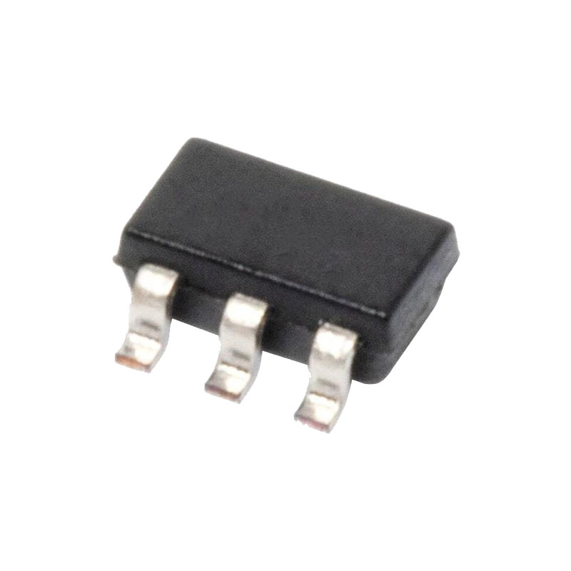
-Packages: SOT23-5 and SC70-5 (SOT323-5)
-ESD performance HBM: 2000 V , CDM: 1000 V
-Automotive qualified
Приложения
-Telecommunications
-Alarm systems
-Industrial equipment
-Networking
-Medical equipment
-UPS (uninterruptible power supply)
-Automotive
Дополнительная информация
Операция
The STWD100 device is used to detect an out-of-control MCU. The user has to ensure watchdog reset within the watchdog timeout period, otherwise the watchdog output is asserted and the MCU is restarted. The STWD100 can also be enabled or disabled by the chip enable pin.
Watchdog input (WDI)
The WDI input has to be toggled within the watchdog timeout period, tWD, otherwise the watchdog output, WDO , is asserted. The internal watchdog timer, which counts the tWD period, is cleared as follows:
1. by a transition on the watchdog output, WDO
2. by a pulse on the enable pin, EN
3. by toggling the WDI input (low-to-high on all versions and high-to-low on the STWD100xW, STWD100xX and STWD100xY only).
The pulses on the WDI input with a duration of at least 1 µs are detected and glitches
shorter than 100 ns are ignored.
If the WDI is permanently tied high or low and EN is tied low, the WDO toggles every 3.4 ms (tWD) on the STWD100xP and every tWD and tPW on the STWD100xW, STWD100xX and STWD100xY.
Watchdog output ( WDO )
When the VCC exceeds the timer startup voltage, VSTART, after power-up, the internal watchdog timer starts counting. If the timer is not cleared within the tWD, the WDO low.
After exceeding the tWD, the WDO goes is asserted for tPW on STWD100xW, STWD100xX and STWD100xY regardless of possible WDI transitions.
On the STWD100xP, WDO is asserted for a minimum of 10 µs and a maximum of tWD after exceeding the tWD period.
The STWD100 has an active low open drain or push-pull output. An external pull-up resistor connected to any supply voltage up to 6 V is required in case of an open drain WDO output . Select a resistor value large enough to register a logic low, and small enough to register a logic high while supplying all input current and leakage paths connected to the reset output line. A 10 kΩ pull-up resistor is sufficient in most applications.
DC and AC parameters
This section summarizes the operating measurement conditions, and the DC and AC characteristics of the device. The parameters in that follow. Designers should check that the operating conditions in their circuit match the operating conditions when relying on the quoted parameters.
(1)Valid for ambient operating temperature: TA = –40 to 125 °C; VCC = 2.7 V to 5.5 V except where noted.
(2) WDO asserts for minimum of 10 µs even if EN transitions high.
(3) WDO asserts for minimum of 10 µs regardless of transition on WDI (valid for STWD100xP only).

