GENERAL DESCRIPTION
The AD3552R is a low drift, dual channel, ultra-fast, 16-bit accuracy, current output digital-to-analog converter (DAC) that can be configured in multiple voltage span ranges. The AD3552R operates with a fixed 2.5 V reference.
Each DAC incorporates three drift compensating feedback resistors for the required external transimpedance amplifier (TIA) that scales the output voltage. Offset and gain scaling registers allow for generation of multiple output span ranges, such as 0 V to 2.5 V, 0 V to 5 V, 0 V to 10 V, −5 V to +5 V, and −10 V to +10 V, and custom intermediate ranges with full 16-bit resolution.
The DAC can operate in fast mode for maximum speed or precision mode for maximum accuracy.
The serial peripheral interface (SPI) can be configured in quad SPI mode, dual synchronous SPI mode, dual SPI mode, and single SPI (classic SPI) mode with single date rate (SDR) or double data rate (DDR), with logical levels from 1.2 V to 1.8 V.
The AD3552R is specified over the extended industrial temperature range (–40°C to +105°C).
FEATURES
16-bit resolution
33 MUPS rate in fast mode
22 MUPS rate in precision mode
65 ns small signal settling time to 0.1% accuracy
100 ns large signal settling time to 0.1% accuracy
Ultra small glitch: < 50 pV×s
Ultra low latency: 5 ns
THD: −105 dB at 1 kHz
Highly configurable output voltage span and offset
1.2 V and 1.8 V logic level compatible
Single (classic), dual, and quad SPI modes
Multiple error detectors, both analog and digital domains
2.5 V internal voltage reference, 10 ppm/°C maximum temperature coefficient
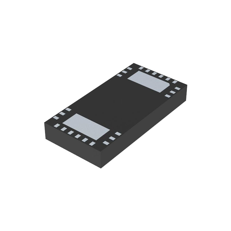
5 mm × 5 mm LFCSP
APPLICATIONS
Instrumentation
Hardware in the loop
Process control equipment
Medical devices
Automated test equipment
Data acquisition system
Programmable voltage sources
Optical communications
TERMINOLOGY
Relative Accuracy or Integral Nonlinearity (INL)
For the DAC, relative accuracy or integral nonlinearity is a measurement of the maximum deviation, in LSBs, from a straight line passing through the endpoints of the DAC transfer function.
Differential Nonlinearity (DNL)
Differential nonlinearity is the difference between the measured change and the ideal 1 LSB change between any two adjacent codes.
Offset Error
Offset error is the vertical deviation from the ideal transfer function after the gain error has been compensated. Offset error is expressed in mV. In the AD3552R, offset error is measured at midscale. The comparison between the ideal output and the actual output is performed at midscale.
Full-Scale and Zero-Scale Error
These errors measure the deviation from the ideal value at full scale and zero scale, at 25°C. The error is expressed as % of full-scale range (FSR). In the case of the AD3552R, the ideal value is calculated as the average of a sufficiently high number of samples.
Full-Scale and Zero-Scale Error Drift
These parameters measure the variation of the zero-scale and full-scale voltage as a function of the temperature, relative to the ideal zero-scale and full-scale voltages. They are expressed in ppm/°C. The total deviation over temperature is calculated using the same formula used for the offset.
DC PSRR and AC PSRR
PSRR indicates how the output of the DAC is affected by changes in the supply voltage. PSRR is the ratio of the change in VOUT to a change in the supplies for midscale output of the DAC. DC PSRR is measured in mV/V, and AC PSRR is measured in dB. VREF is held at 2.5 V, and the supplies are varied by ±200 mV p-p.
Output Voltage Settling Time
Output voltage settling time is the amount of time it takes for the output of a DAC to settle to a specified level within a given accuracy for a given step change. Typically, it is evaluated for a small step and a large step to account for the effect of amplifier slewing.
Digital-to-Analog Glitch Impulse
Digital-to-analog glitch impulse is the impulse injected into the analog output when the input code in the DAC register changes state. It is normally specified as the area of the glitch in nV × sec and is measured when the digital input code is changed by 1 LSB.
Digital Feedthrough
Digital feedthrough is a measure of the impulse injected into the analog output of the DAC from the digital inputs of the DAC, but it is measured when the DAC output is not updated. Digital feedthrough is specified in nV × sec and measured with a full-scale code change on the data bus, which means from all 0s to all 1s and vice versa.
Total Harmonic Distortion (THD)
THD is the difference between the sine wave played by the DAC and an ideal sine wave of the same frequency and amplitude. The deviation from an ideal sine wave is due to time and amplitude discretization and nonlinear distortion. THD is measured as the power ratio of the sum of harmonic components to the fundamental component. It is expressed in dB.